
Cykong's original document dealt with rack mounting a mc202.
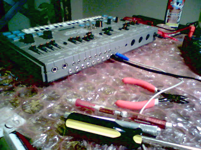
I have modded a 202 using those instructions, but kept my 202 in it's original case (see picture above).
The mods are such that the 202 can operate modded, or in it's original vintage condition.
I was able to fit 10 jacks and 4 toggles
onto the 202, but with more work you may be able to fit 11 or 12 jacks
(or more if you mount the extras in locations other than the back...)
Original Roland MC-202 schematics for reference (not needed using this guide):
10 Mods Listed in order:
| Parts List For all Mods below | |
|---|---|
| 10x 1/8" switched mono jacks | 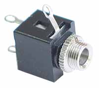 |
| 4x 100k resistor (1%) |  |
| 4x SPDT (on-on) sub-mini toggle switch | 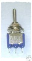 |
| thin stranded wire (28AWG ribbon cable) |  |
| 1/16" dia heatshrink tubing |  |
subatomic: WARNING: The black and white PCB
pictures below are flipped right-to-left!!!
Think and plan carefully
before doing work. Understand and identify your locations...
1a,2a.) Proper CV / GATE INPUTS
Note: If you're not rackmounting the MC-202, you'll need to wire a few more wires for the bypasses. Bear in mind that: we'll be patching the proper CV/Gate AFTER the internal sequencer, so bypasses are needed if u require the internal sequencer CV/Gate to pass thru. See below "using Switch Sockets"...
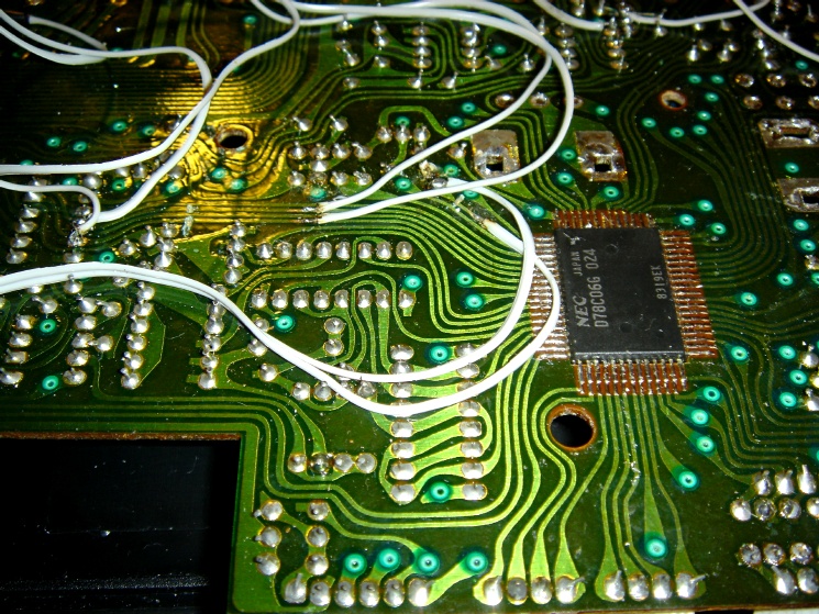
1. Proper CV IN IC15 is located on the right of the rectangular cut in the
middle of the PCB (face from top/component side), bottom left of the
ACCENT Pot, right top corner of the LCD Display area.
So, facing from the PCB Track side....
2. Proper GATE IN
So, facing from the PCB Track side....
1b,2b.) Proper CV / GATE INPUTS (using Switch Sockets)
CV Mod with Switch Socket:
Gate Mod with Switch Socket:
Or, you can wire a switch to switch between Internal or External CV/Gate:
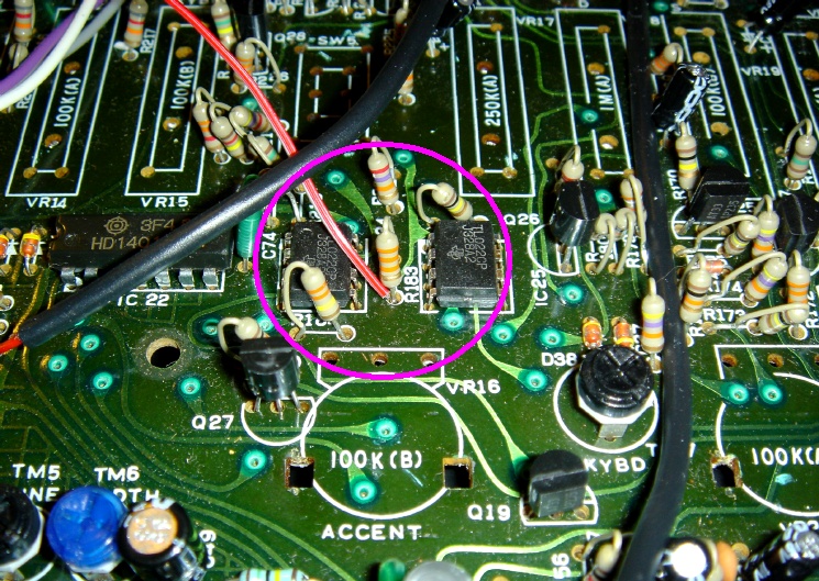
3.) VCF Cutoff cv (input)
IC24 is located on the middle right of the PCB (facing from
TOP/Component side), just under SW5 (ENV/GATE Switch) and the ATTACK
(ASDR) Slider, above the ACCENT Pot.
Or you can do it on the other side...facing from the PCB Track side....
Note: There's no need for switched sockets for the VCF CV input. When a jack is plugged in, the CV is ADDED to the VCF Cutoff Frequency slider setting. However, if you're wiring these CV In's directly to an internal midi interface or if you'll be constantly having the additional CV jacks plugged in, it is better to have a switch for the CV in. Just a simple SPST to switch the CV IN.
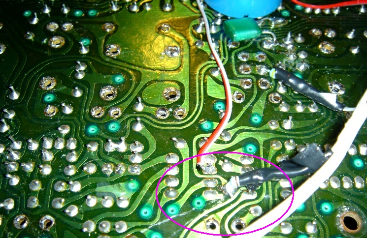
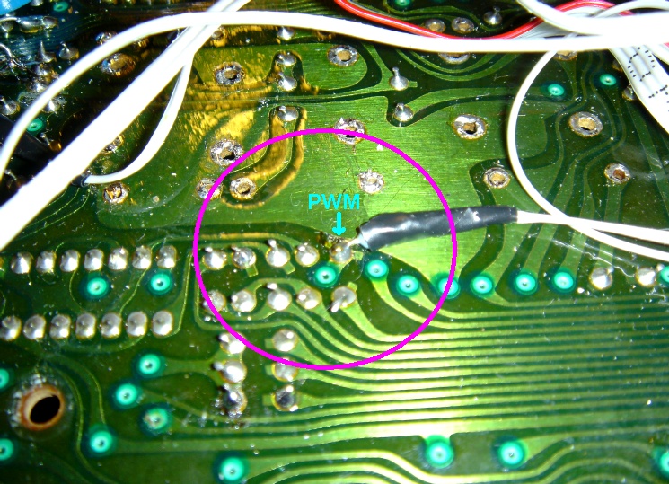
4.) PW cv
So a socket with a 100k resistor, tapping to either the PWM Slider or the leg of R191 will provide PWM CV IN.
R191 is located just underneath the ENV Slider in the VCF Section
So, facing from the PCB Track side....
Note: There's no need for switched sockets for the PWM CV input. When a jack is plugged in, the CV is ADDED to the PWM Slider setting. However, if you're wiring these CV In's directly to an internal midi interface or if you'll be constantly having the additional CV jacks plugged in, it is better to have a switch for the CV in. Just a simple SPST to switch the CV IN.
5.) VCA (limited Volume Control)
Again, a socket with a 100k resistor tapping to the middle of SW5 near the BLUE round internal speaker.
Either side would do, as they're linked together.
So, facing from the PCB Track side....
NOTE: The VCA CV In doesn't produce any dramatic effects, it acts like an extra Volume Control, but the width is very limited.
6.) MOD
Actual MOD on the MC-202 goes from the LFO Sine output to the MOD Slider. So it is possible to tap a CV IN to the mod...
Note: The Analogue Solution Modular Upgrade MOD CV IN
is kinda confusing. In fact, whatever was done on this MC-202 wasn't
working properly. What the AS Mod CV IN is doing, is actually adding the CV to the Mod Slider, but CUT/Disconnect it from the slider to the LFO Sine Output from IC9. A "Mod Contact" wire linked the Mod Slider back to where it's supposed to be going...
It may be easier to actually do a switch to select the MOD from MOD CV IN or LFO Sine Out.
This way, there's no need to tap to the slider, and just one cut is needed.
On the solder side:
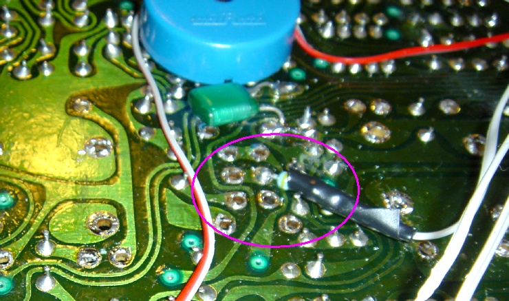
7.) PORTAMENTO CV SWITCH INPUT ( +5V will turn Portamento OFF. 0V will turn it ON. )
Track cutting is required...
Note: +5V will turn Portamento OFF. 0V will turn it ON. (I have this assigned to Midi CC#65, but the effect is reversed).
8a.) ACCENT (VCA) CV SWITCH INPUT ( +5V will turn ACCENT ON. 0V will turn it OFF. )
Track cutting is required...
Note: +5V will turn ACCENT ON. 0V will turn it OFF. (I have this assigned to Midi CC#64 - Sustain Pedal).
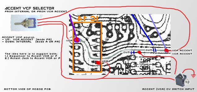
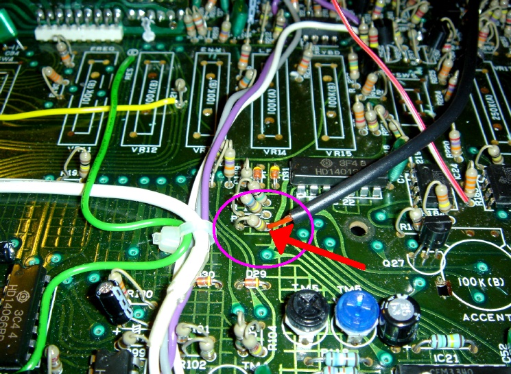
8b.) ACCENT (VCF) CV SWITCH INPUT
Track cutting is required...
Note:Well, at 1st I didn't do this mod... as I've run out of Aux Gates.... But after writing up this page, i decided to give it a try, and used a SPDT switch to switch my Aux Gate going to either the Accent VCA or the Accent VCF.
So... the PCB side of things:...
CUT TRACK: the track under the IC is wider and easier to cut
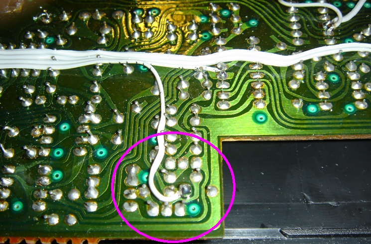
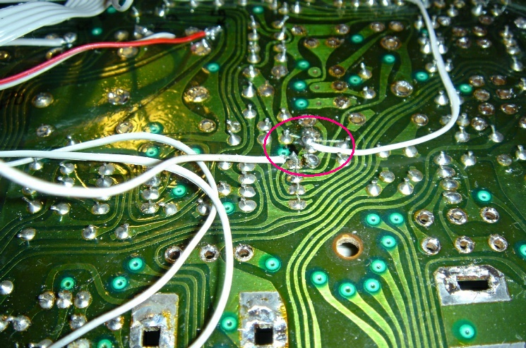
8c.) Selector for Accent -> VCF/VCA (toggle switch)
I use a switch from a MIDI AUX GATE Out to switch between going to the VCA ACCENT and the VCF ACCENT. However, I found that the Accent VCF will only work IF ACCENT VCA IS ALSO TURNED ON. So on my switch, i actually have the AUX GATE and the Accent
VCA wired together. When switched, AUX GATE is going to BOTH Accent VCA
and Accent VCF, and this actually activates the Accent VCF. As you can see, the YELLOW Aux Gate wire is also wired to the Accent (VCA) on the right.
subatomic: I found this very confusing, so I came
up with a solution for the ACCENT VCA and ACCENT VCF
9.) Ext Audio Input to VCF Source Mixer
So either use a socket and a 100k resistor, or a socket + 100k + 100k Pot tapped to the common point of the legs of R186 / R187 / R188.
R186 / R187 / R188 are located just underneath the Filter ENV / MOD / KYBD Sliders.
10.) Ext Audio Input to VCA
R147 / R148 are located below the Volume Pot.
extra: Bareille midi2cv kitsubatomic: a good option for midi-fying your mc-202 after doing the above mods. this is the kit cykong used in his rack |


