Subatomic Midibox SID V2 worklog
|
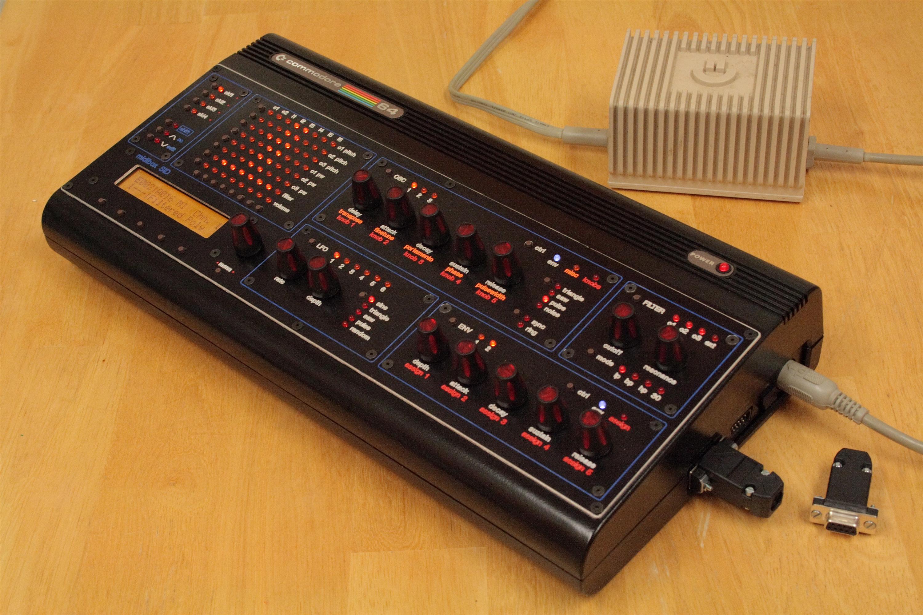
This is the worklog for my MidiboxSID, a synthesizer that has sound
chips
from the original commodore 64 personal computer from the
1980's. These sound chips are called the SID
6582 The synth is built into an original Commodore 64 computer case. And features 8 SID chips (4 stereo pairs - one SID per ear x 4 voices). Each SID chip has 3 oscillators and a variety of other features like filters, ADSR, ringmod, sync. The synth has a very flexible (and simple to use) modulation matrix, LFO, bassline sequencers, and stores patches in presets.
What follows is my build log, detailing progress until the synth was finished:
UPDATE:
|
Late 2005'ish
sourcing lots of parts, getting everything planned. I have...
4 CORE
4 SID
2 DOUT
3 DIN
1 LTC
from smash tv + a bunch of encoders, 1/4" jacks, heatsinks, midijacks, tact switches from various places on the interweb.
1.31.2006
7:30pm-9:30pm Put together a SID module, first one, lots more to go...
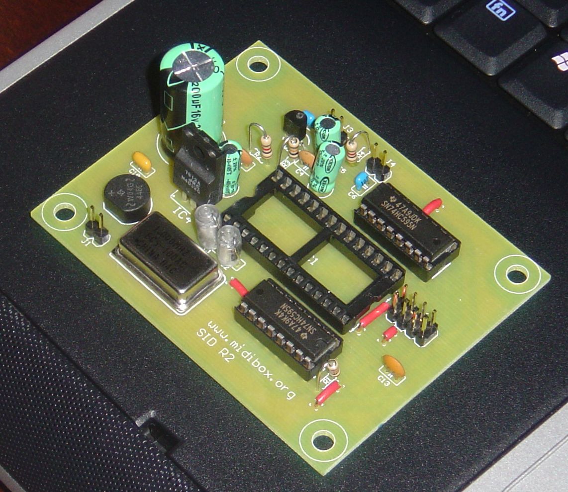
Put together my first module, a SID module...
2.05.2006
11:00am-4:30pm ceedub stopped by with burned PICs and a c64 case for me, whoohoo... We spent the day ripping the case apart, soldering modules and attempting to connect two modules together (using connectors/headers and crimping wires to pins), then we realized we didn't have a source of power - we need to build a filter board to change the 9VAC and 5VDC from the original c64 power supply adaptor to 14VDC and 5VDC useful by the SIDs and cores (respectively). We call it a day and go work on some music together.
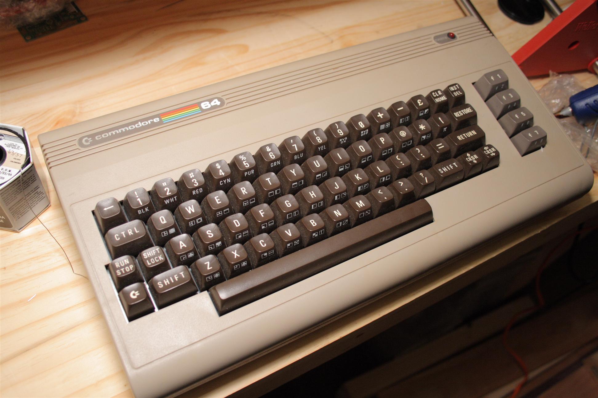
The new commodore 64, soon to be dismantled
2.06.2006
8:00pm-10:00pm Used Thorsten's "optimised" power supply diagram to build something that takes the original c64 PSU and converts it to 14VDC and 5VDC, with an additional low current connection for the case LED. This new board will fit the c64 case perfectly preserving the old power inlet, serial conectors, and on/off switch locations.
2.07.2006
7:00am-8:00am Finished the power board. It ended up pretty skinny, which is good, because I'll need to fit in 4 of the core and SID modules as well as an active audio mixer board. The c64 case is getting tight, but I think will still work. I'll hook up the serial connectors later.
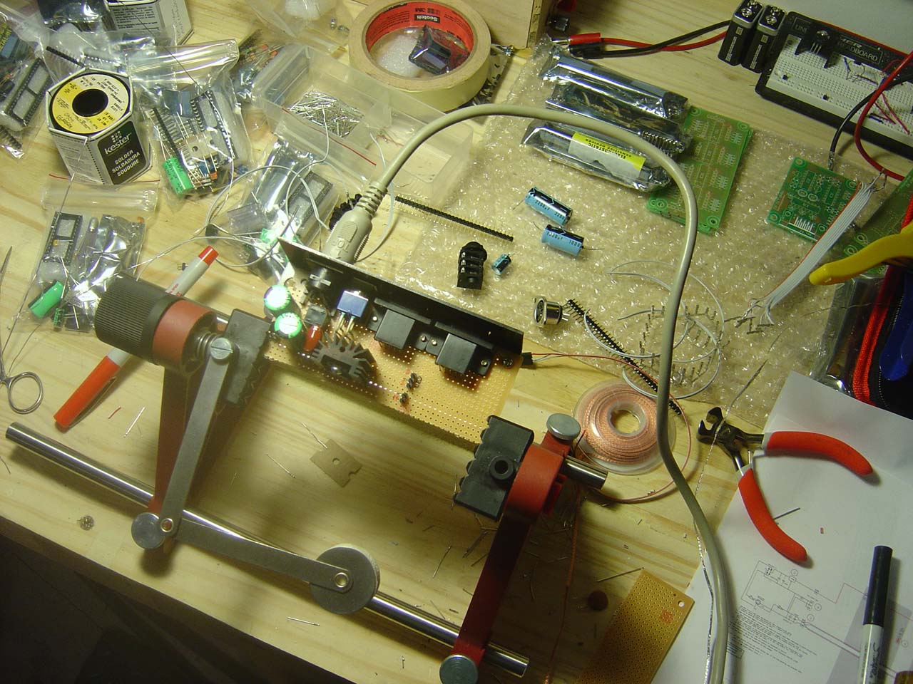

The finished power board, converts the c64 power adapter to 5VDC and
14VDC. Also has an on/off switch, and two serial ports - to be used
by the banksticks, a removable memory stick for the MidiboxSID's
patch memory
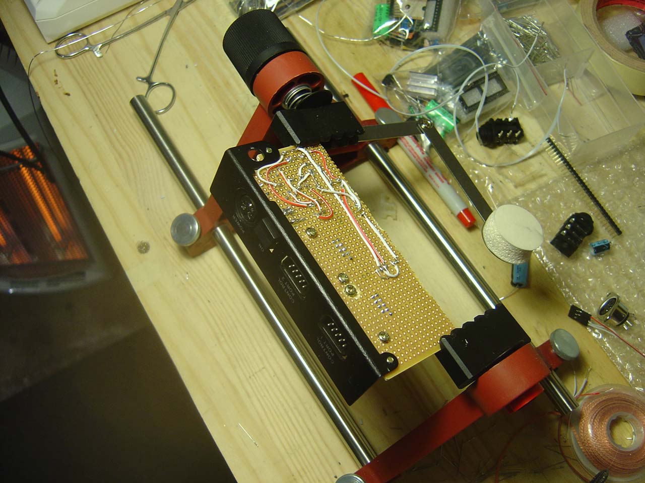
Installed the power board into the c64 case, nice fit, you'd never
know it's not a c64 inside by looking at this panel...
06.09.2007
3pm I ordered "waldorf" knobs from albs.de (Germany), part number 863062. These are out of production, but I managed to order 90 for myself, ceedub (chris) and sdclements (steve)... Took 4 days to ship over from Germany to the US... About $1 each knob, not too bad!
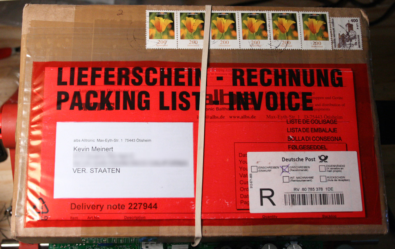
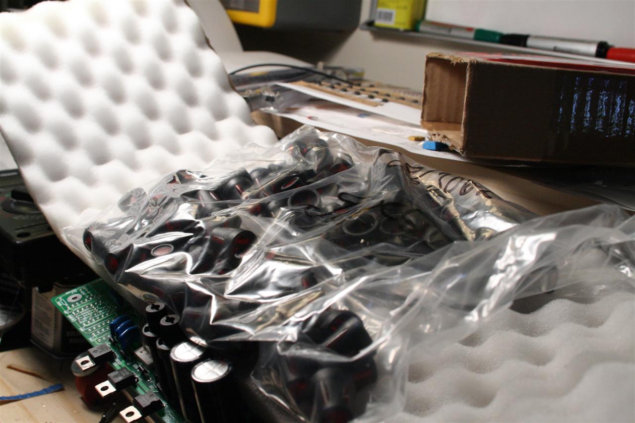
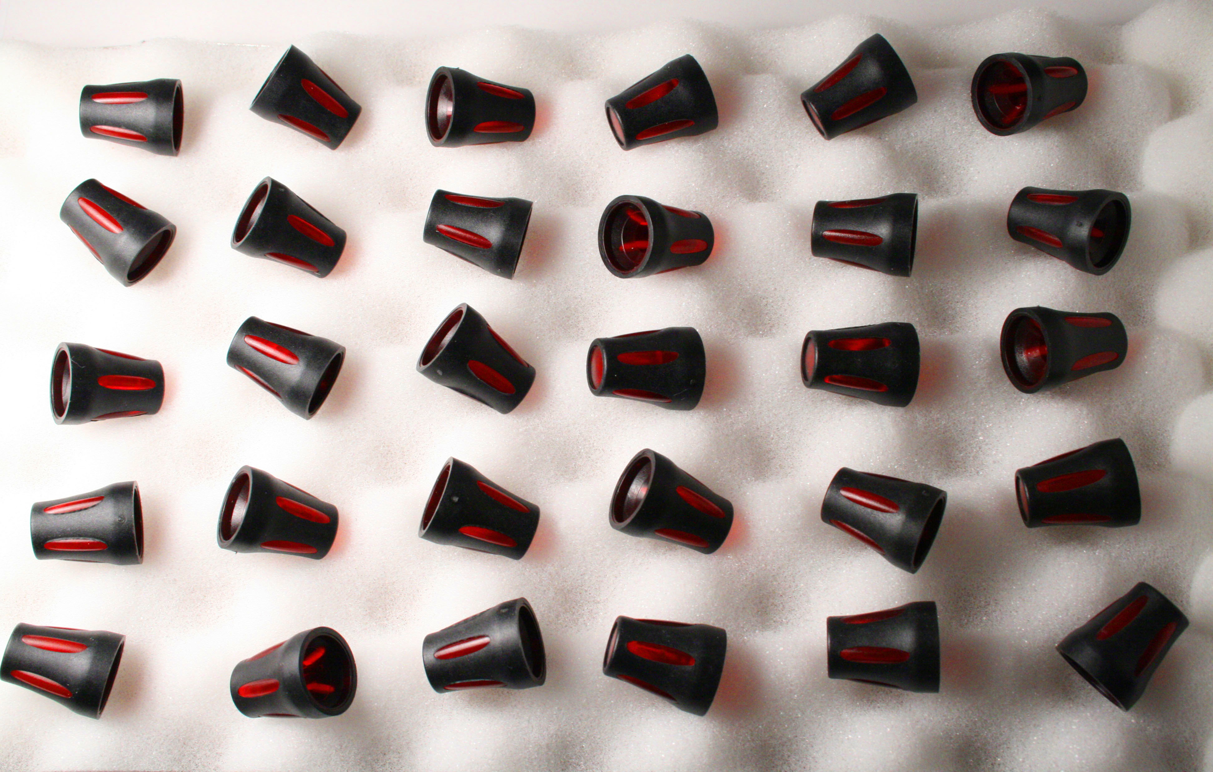
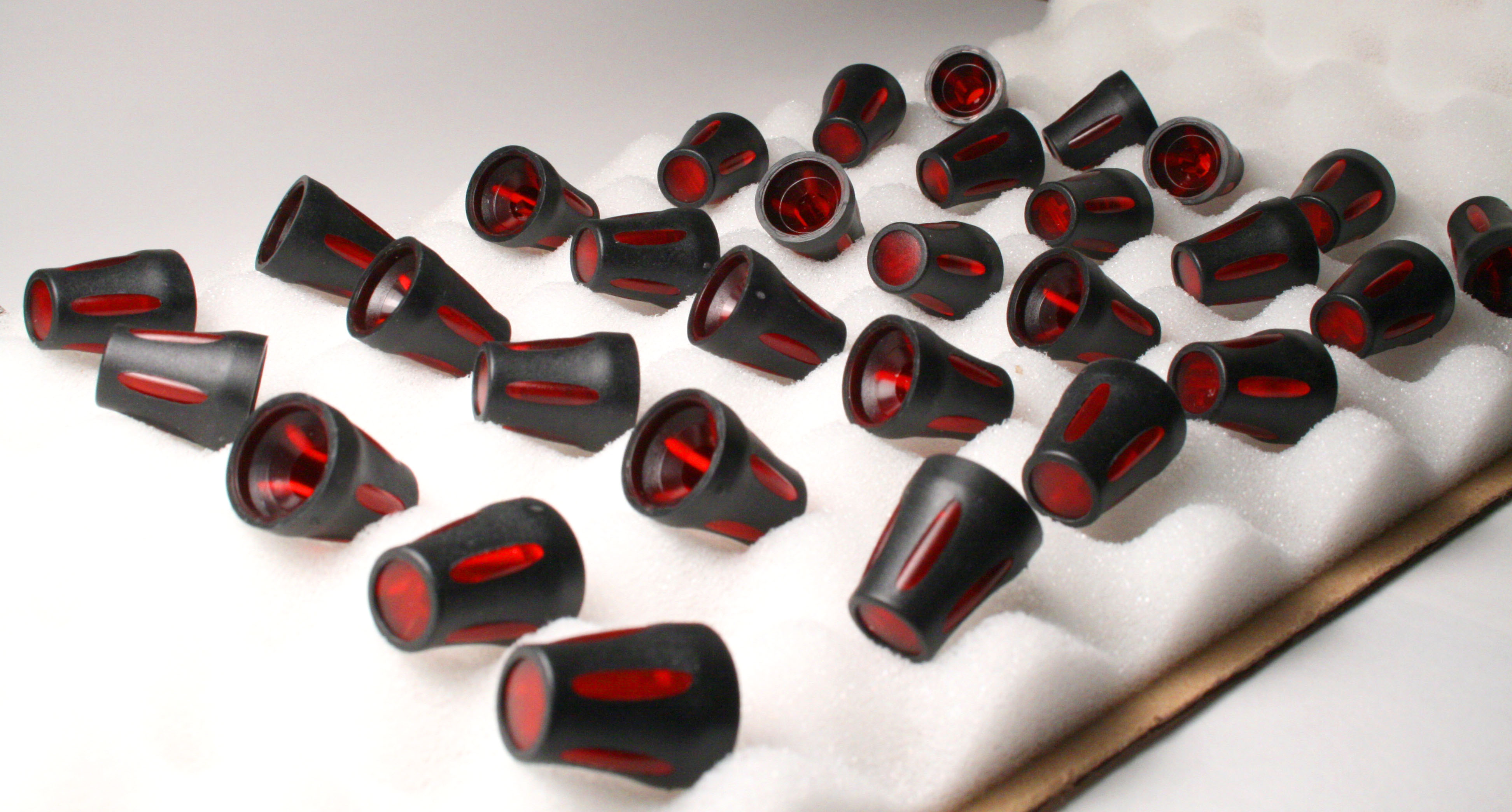
Waldorf knobs arrived!
07.21.2007
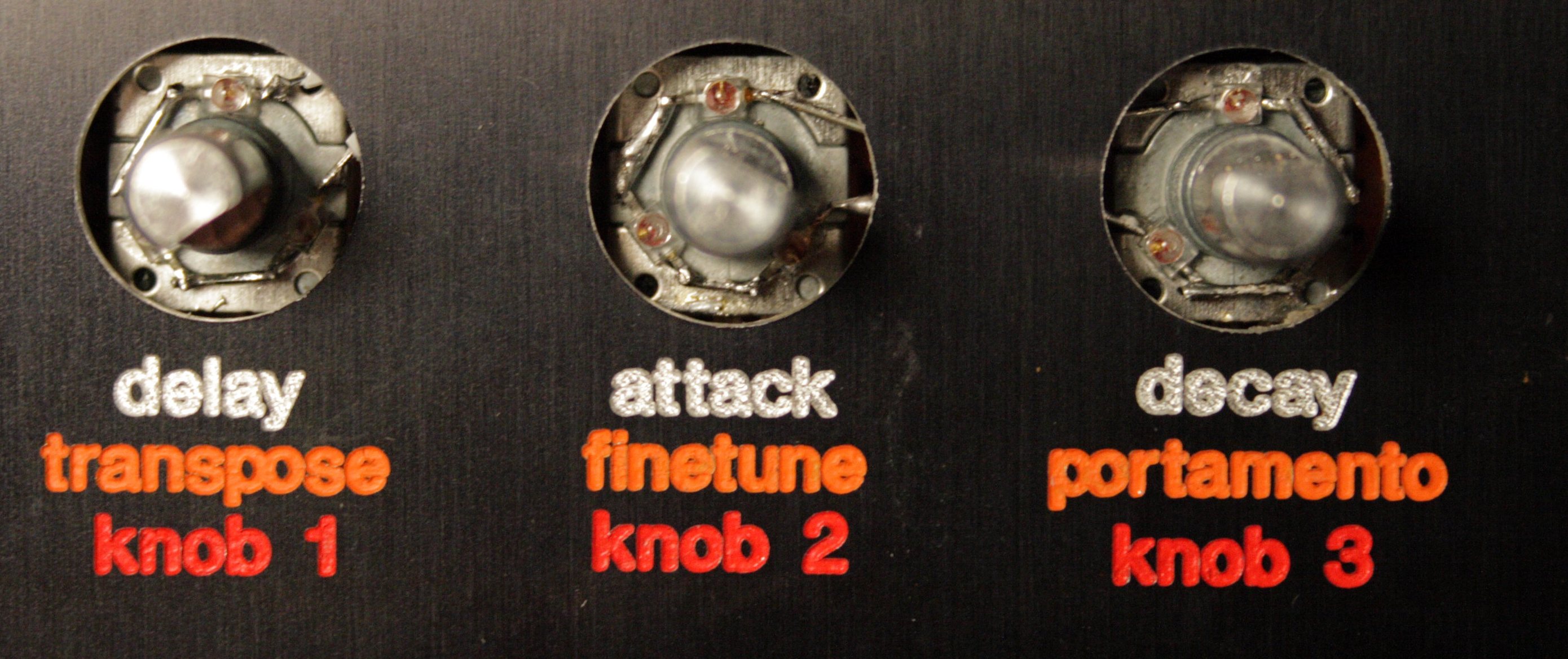
12-2am Finished a mockup of the panel design for the sid synth... I was trying to decide between TK's original retro beige and a black design... I caved in for the hot black design. :) After doing a few designs in front panel designer, doing some google image searches, crystalfontz and taking pictures of the knobs I already have, I was ready to piece this mockup together...
I plan to use tinted LEDs, so you can see the color of the LED when it is off, and so that they glare less, for a nicer effect during use. red and orange only (with 2 whites). I also plan to back-light the transparent knobs. The knobs have a clear red plastic in them, so it will be possible to light them from underneath to make them glow red. For this I plan to use some tiny surface mount (SMD) LEDs glued to each encoder. To let the light shine through, the encoder holes on the panel must be big enough to let the light through (this means I can't use the panel-mount nuts to fasten the encoders to the panel, so the PCBs will also need to be reinforced to prevent flexing).
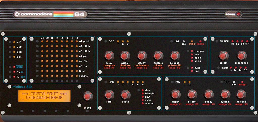
1.) Previs of the black box I plan to build...
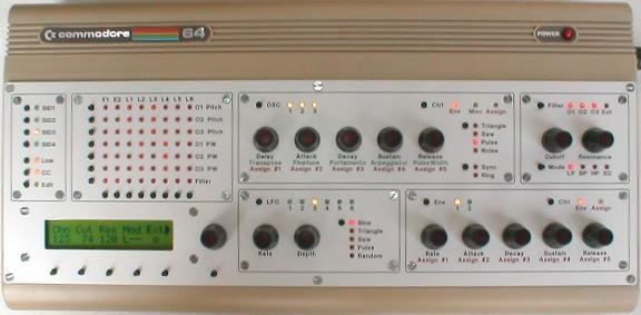
2.) TK's original beige-box retro SID...
mbsid_panel.fpd (panel layout)
mbsid_panel-KnobLEDs.fpd (panel layout with oversized encoder holes for LED lighting)
07.22.2007
Tonight, doing some reading up on the midibox, planning the panel mainly. Reading up on V2 panel features so that I design this panel right, and talking with wilba over PM on the midibox forums about best ways to mount components to the PCB...
12am wilba mentioned that he's using 13mm long tact switches, which make it so that the control surface components can be mounted to a single PCB... so I did some research. looks like mouser has them:
Mountain Switch
- 101-TS7311T1607-EV ($0.16)
- 101-TS6111T1607-EV ($0.18)
(both are 6.2 x 6.2mm x 13mm high with 160g operating force)
ESwitch
- 612-TL1105D ($0.18 160g)
- 612-TL1105DF100Q ($0.14 100g)
(6x6mm x 13mm high)
ALPS
- SKHHDTA010 ($0.56 100g) (this is what wilba's using, pics here)
(6x6mm x 13mm high)
1am (just checked) luckily i already have a big bag of these... :)
2am Regarding panel thickness... from here, Wilba says:
The panels to suit the PT-10 case are 1.5mm aluminium, and this thickness is required to make the switch shafts and rotary encoders poke through the panel the right amount.
He's using the waldorf knobs as well. and says that the knobs fit "just right" when using 1.5mm panel thickness... (I have no idea if this is strong enough over the length of a c64 case, as he was using a smaller case for his panel...)
He's using 13mm high tact switches with 7.5mm base height encoders. (the encoders I have from smashtv measure the same)... Wilba strongly advocated doing the same (in a PM to me) in order to avoid layering of PCBs to achieve the right heights (which would be a pain in the ass well worth avoiding)...
07.23.2007
11-1am Started prototyping the control surface a bit. Printed it out and started test fitting a few pieces. I soon discovered that I needed to align the components to 0.1" spacing (which matches PCB perfboard spacing). I spent some time on the .fpd file and now everything is aligned so that I can put each section on a single PCB...
I also added a 'midibox SID' logo to the panel so people would know what the hell this thing is... (and to give TK's project the credit it deserves)
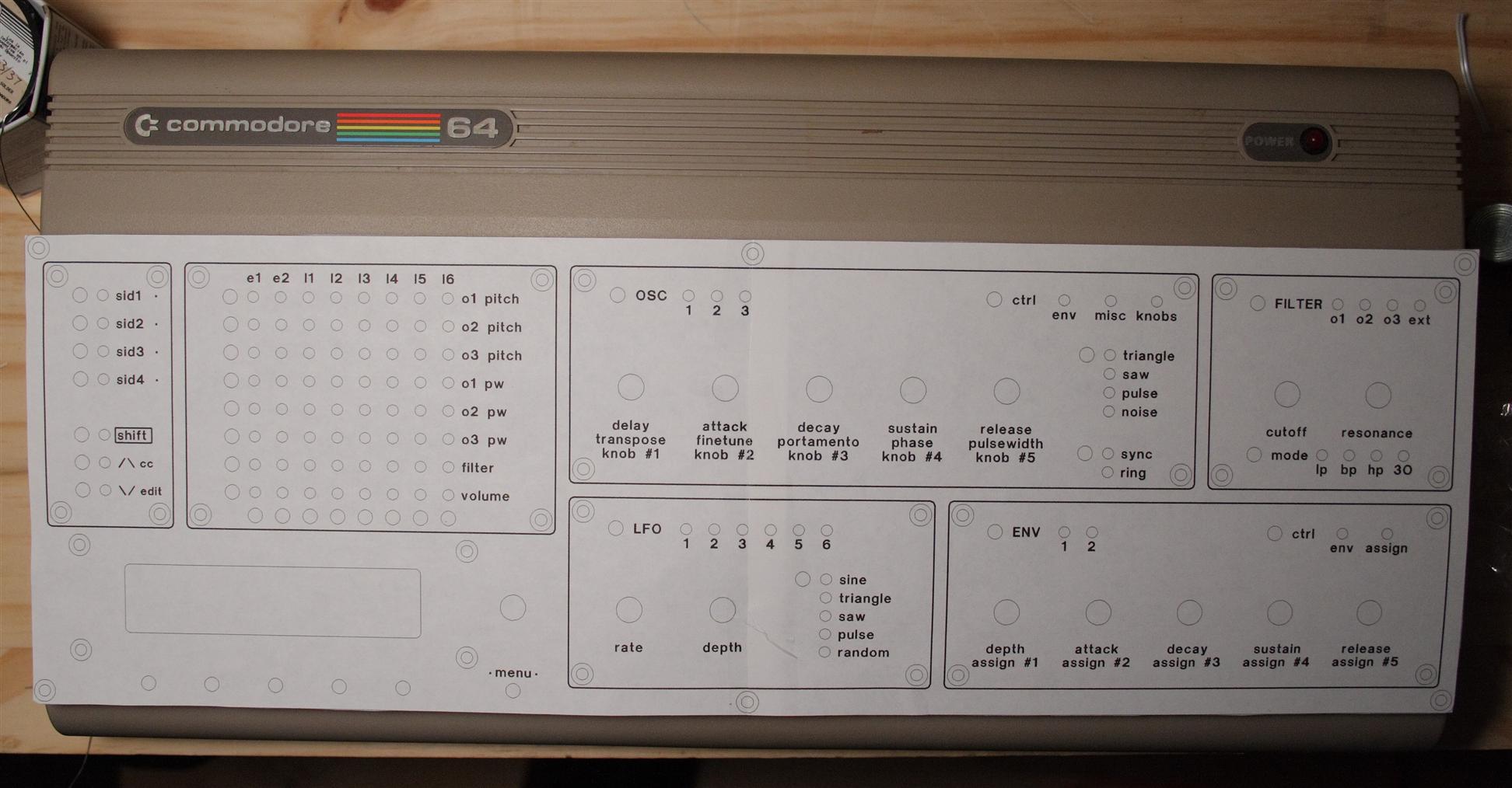
1.) Checking out the panel before sending off to be printed
2.) Added a midibox SID logo
07.27.2007
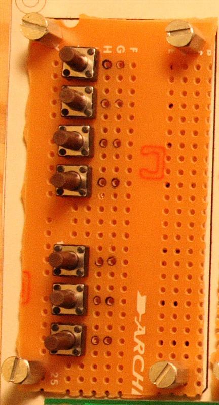
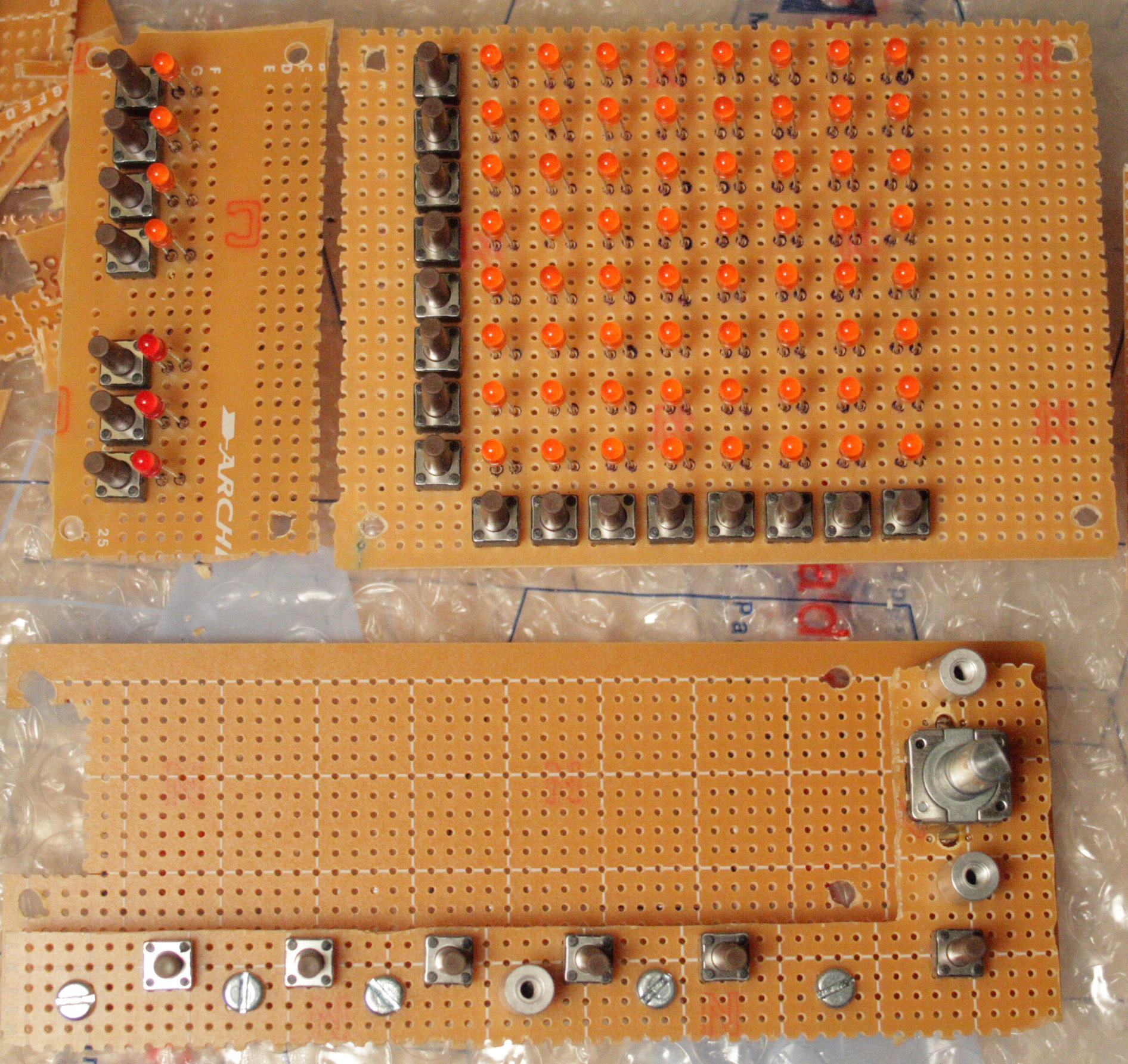
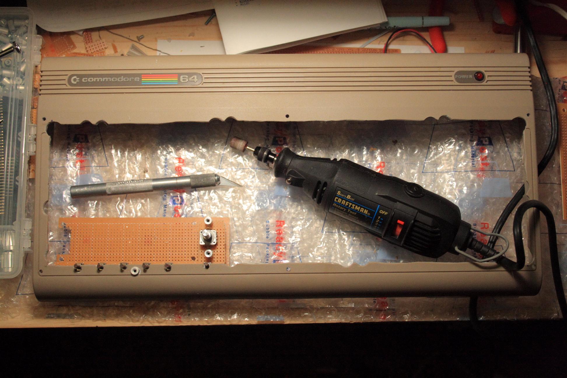
8pm Built the filter control surface PCB. I'm assuming a 1.5-2mm thick aluminum panel. As a result, I have 9.5mm spacers, and 8.5mm LED standoffs (to account for the 1mm LED base edge). The buttons are 13mm high starting at base, and encoders have a 7.5mm high base. I used cheap hard plastic tubing I found at the local hardware store, it's the kind that's used as a drip hose for gardening, refridgerator ice-maker lines, fish tanks... 'Rain Drip' 50 feet of 1/4" tubing was about $6... easy to cut with exacto knife, it's far less cost than aluminum threaded spacers at $0.38 each at mouser. Doing the math, my plastic tube spacers cost about $0.00393 (1/3 of a penny each). I used heat shrink tubing for the LED standoffs.
Using unthreaded spacers requires long screws through to the back, with a nut on the end. I may still need some hidden aluminum spacers under the panel to straighten some of the natural warp, and to reduce bending, on the larger PCBs... Per Wilba's recommendation, these "interior" spacers would be aluminum and glued to the panel using JB-Weld. I think I could instead JB-Weld screw heads to the panel, and use my plastic spacers as before... The point of glueing is to keep the control surface looking good (no random holes).
UPDATE: I ended up using aluminum threaded spacers instead... and no jbweld needed so far...
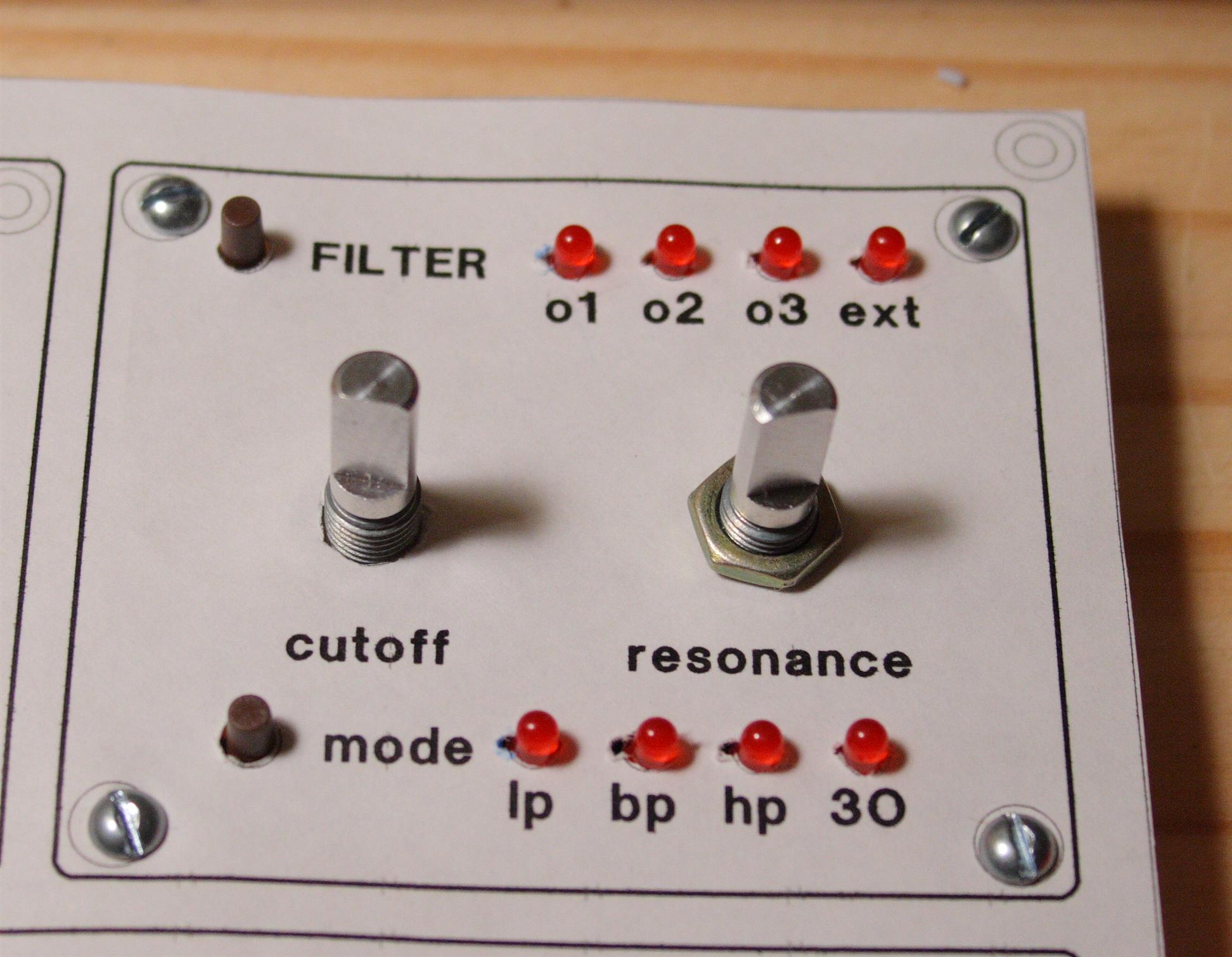
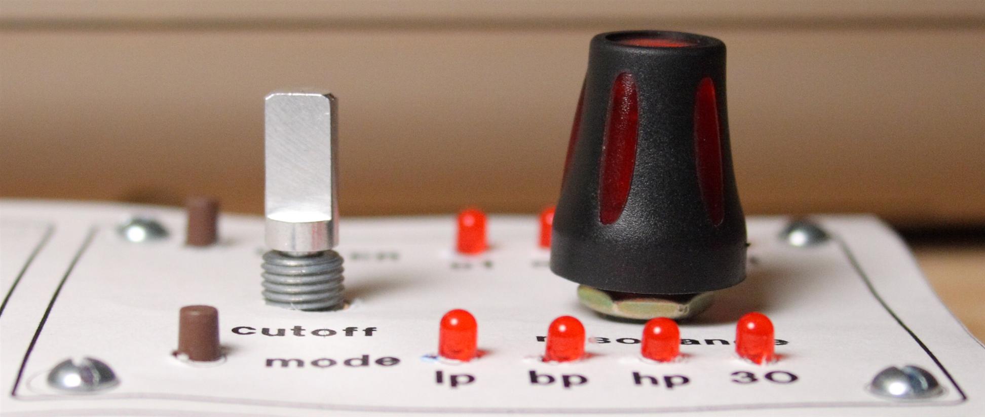
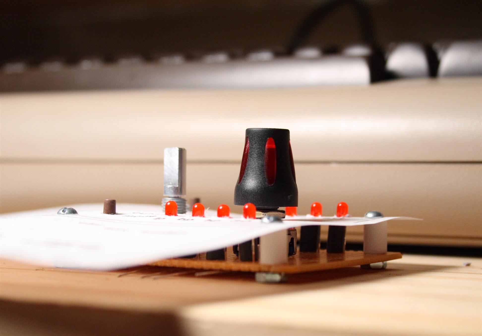
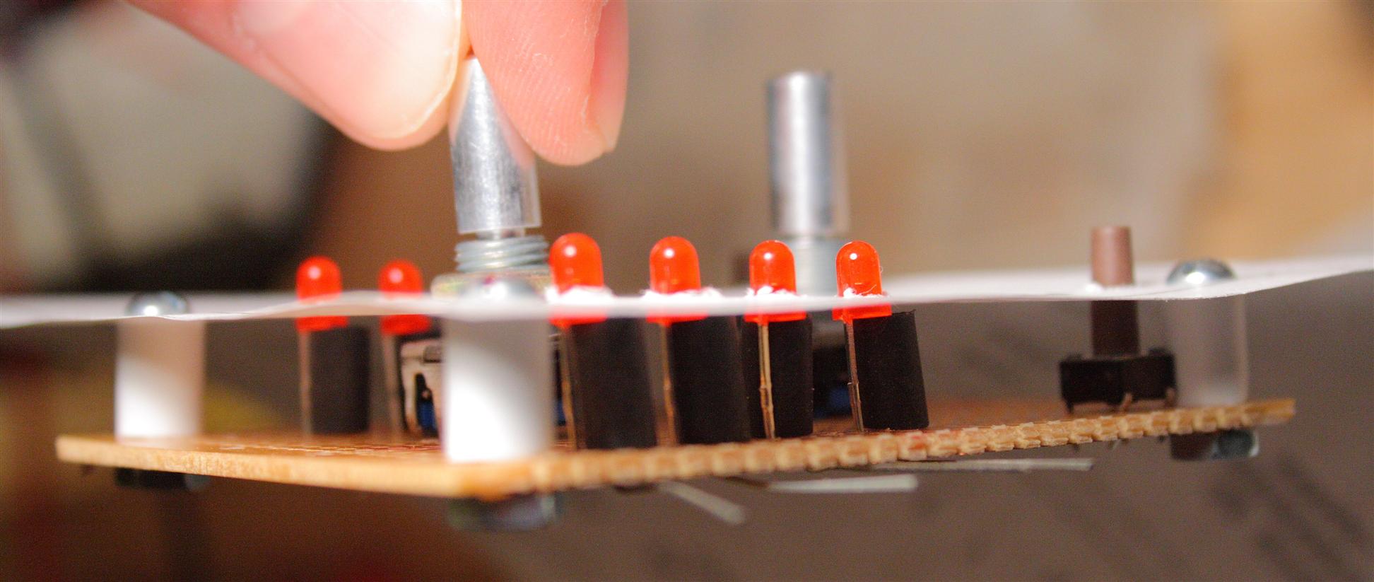
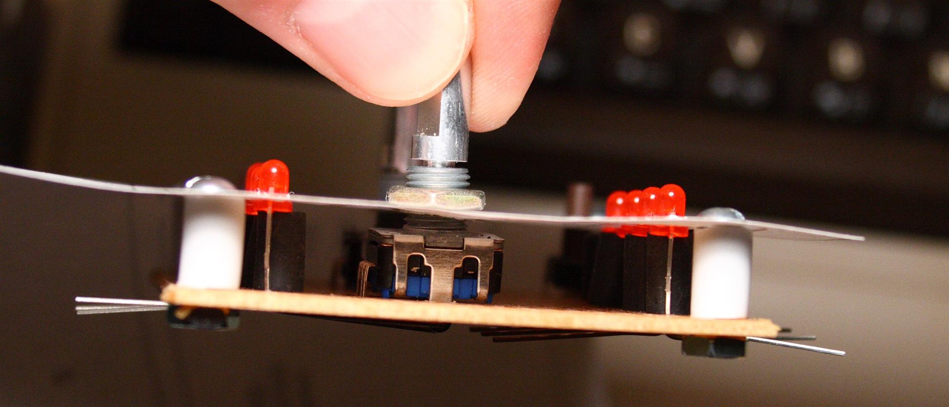
Built the Filter section control surface, test fitting onto the paper panel printout
07.29.2007
11pm Sourcing some parts for the control surface. LEDs and screws.
80 orange  in orange diffuse 3mm package   Kingbright   30mcv (brightness)   40deg
24 red     in red diffuse 3mm package      Kingbright   50mcv                40deg
2 white    in water clear 3mm package      LiteOn     1100mcv              45deg
45 SMD red  in water clear 0805 package   Kingbright   150mcv 110deg
34 threaded aluminum standoff 0.375"  4-40
34 pan head screw 0.25"  4-40
34 flat head screw 0.25"  4-40
    - find black metal oxide screws instead!
2   3-pin  molex connector + header (polarized 0.1" spacing)
9   6-pin  molex connector + header (polarized 0.1" spacing)
4   8-pin  molex connector + header (polarized 0.1" spacing)
3   12-pin  molex connector + header (polarized 0.1" spacing)
1   14-pin  molex connector + header (polarized 0.1" spacing)
142 molex crimp pins
106 8.5mm LED standoffs, or heatshrink cuts, plastic tubing, etc...
I want black screws, but I couldn't find any at mouser or digikey.
I also found 100 white LEDs for super cheap from some hong kong eBay'er... for about the same price as 4 from mouser... crazy what USA companies charge for "exotic" (white/blue/purple) LEDs, c'mon! these colors aren't exotic anymore...
I counted the molex connectors by counting number of components and pins they have + 1 voltage connection + some extra pins for redesign wiggle room. Will probably be good to order extras of each just in case, a lot of this control surface will be (re)designed on the fly, i'm sure...
additionally, because I wont be panel mounting my encoders, because I have red translucent knobs and I want underlighting to make them glow, I will need some additional standoffs welded to the underside of the panel (using jb weld or glue). I think about 10 more pan heads and standoffs should be enough for this.
+10 threaded aluminum standoff 0.375"  4-40
+10 pan head screw 0.25"  4-40
Optionally, if I wanted to use 9.5mm plastic tubing as standoffs ($0.003USD ea), then I can instead use longer screws with nuts:
34 flat head screws 4-40 nickel/steel  0.75"    Keystone
34 4-40 nuts
This "cheap standoff" idea sounds appealing, but a few of the sections would still need additional reinforcement for how wide they are and because PCBs flex and we might not be panel mounting the encoders (so that the SMD leds shine through), so additional standoffs might still be needed (glued to the inside of the panel using JB weld or whatever). People without translucent knobs should be able to simply panel mount their encoders for reinforcement...
Will need a few more perfboards as well:
perfboard
     - these aren't long enough for 2 of the control surface sections!
07.31.2007
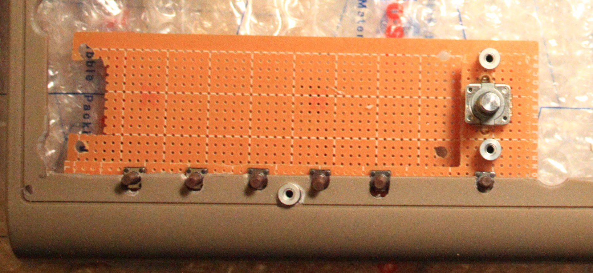
11-1pm Made up a few of the control surface PCBs. I need to order LEDs before these are ready to install. I found some 0.375" (9.5mm) threaded aluminum standoffs that I already had, they seem to work nice. I also soldered on header pins to the LCD...
control surface PCBs
08.25.2007
11-2am Created an LED backlight for the knobs tonight. Based on 2x1.25mm SMD red LEDs, I created a paper ring, superglued them to the ring, applied a little flux to each light, then carefully soldered hair-thin wires between each LED in series. The result is as pictured below, pretty cool! I used this great resistor calculator to compute the ideal resistor to use for each backlight ring, 2.7 ohm (5V supply, 3 leds in series, 20mA (from datasheet) and 1.65V (measured) drop across each)...
These LEDs are _tiny_. It took me a few hours to think of how to pull this off. Once I had the plan, it only took about 15 minutes to assemble one encoder's backlight. Since they're so tiny, the key is to first glue them down to something so they don't blow away, or stick to your solder iron. I cut out a little paper disc to fit around the encoder. From there it's pretty easy to solder the LEDs using a fine tip iron + some flux to get them to easily accept solder. I used paper discs, they scorch a little, so maybe another material would be better for the remaining 14 discs... ideally, super thin PCB with copper pads would be great... then just glue them down to the encoder when done. Will probably complete the rest with paper.. :)
Knob Illumination...
UPDATE: while this was a neat idea, and worked well enough. Wilba pointed me to a much better style of LED, that is much easier to work with. I scrapped the paper rings in favor of gluing a totally different type of LED directly to the knob surface. Check it out here
08.30.2007
SteveM got back to me today, he started CNC work on the front panel. Looking good!
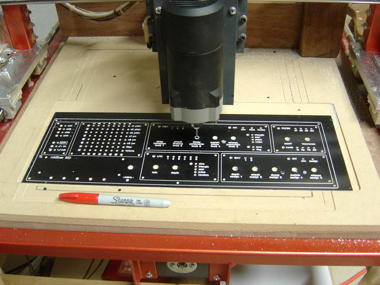
Front panel milling in progress...
11.03.2007
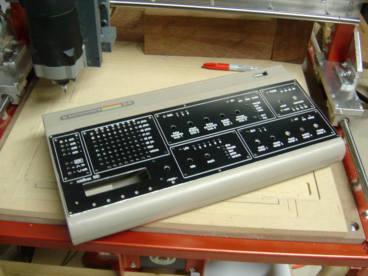
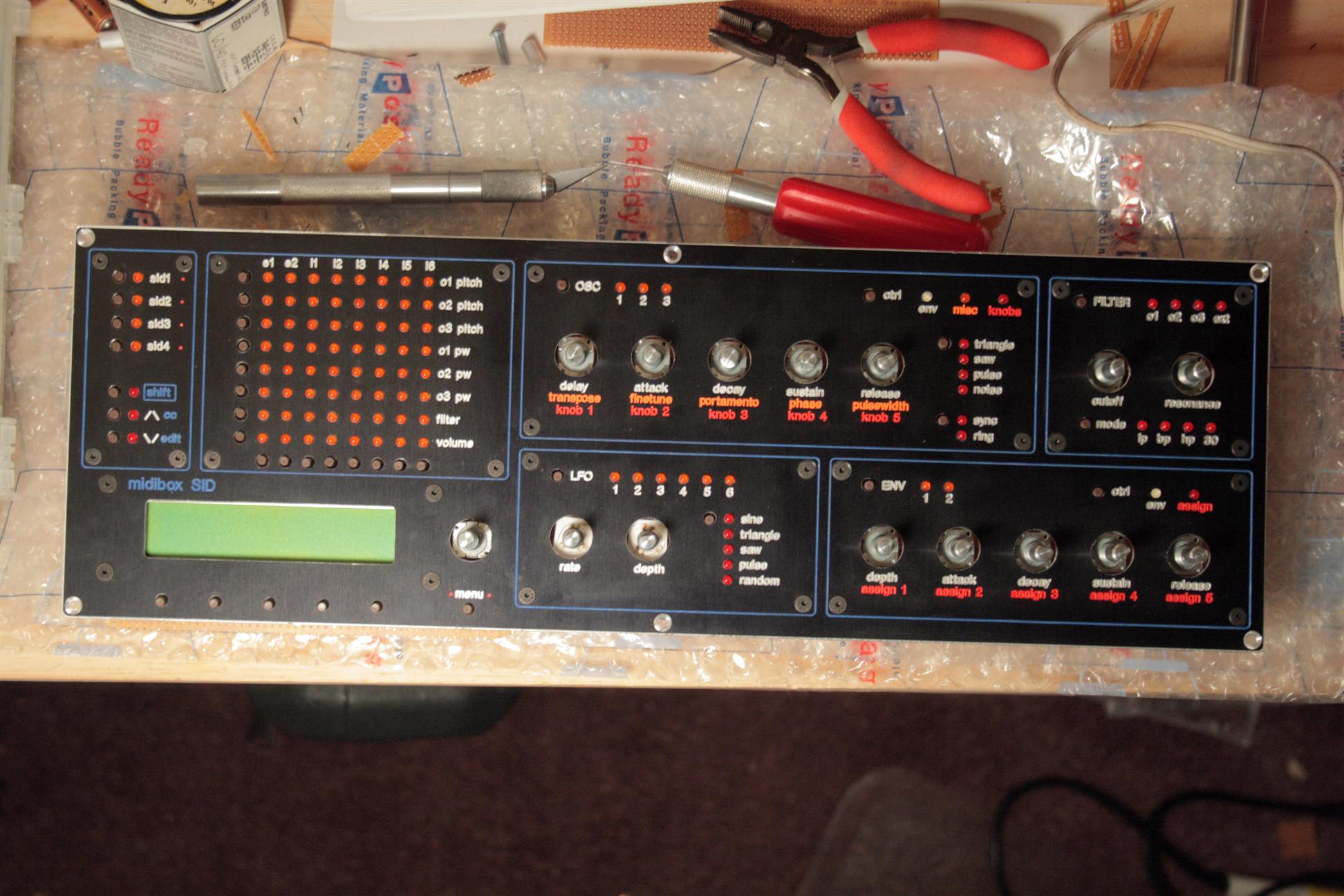
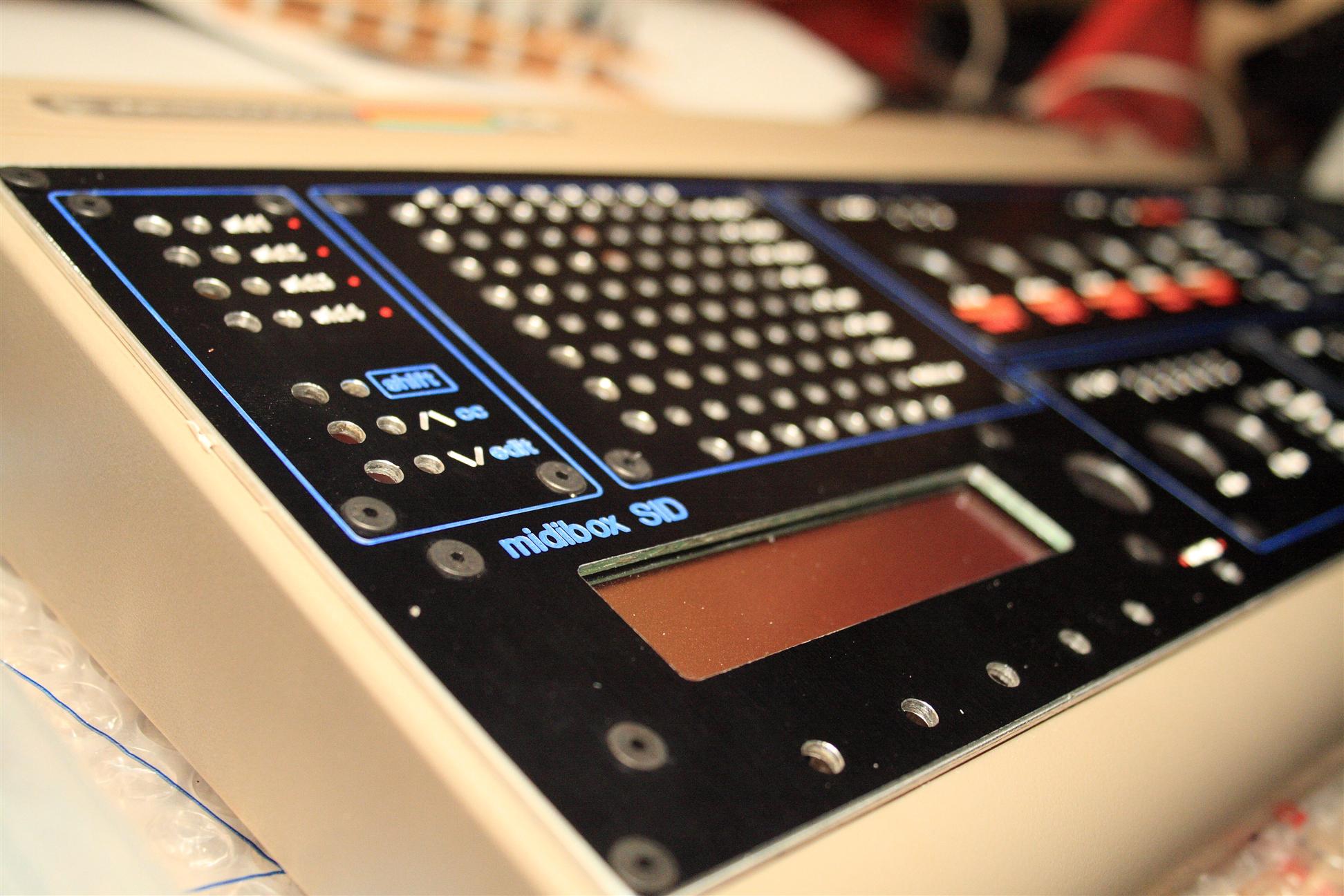
Well, it's hot off the mill. SteveM mailed the new mbSID front panel, and it looks great, check it out:
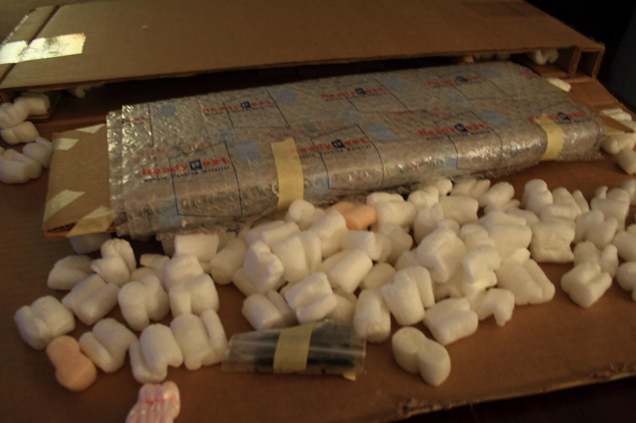
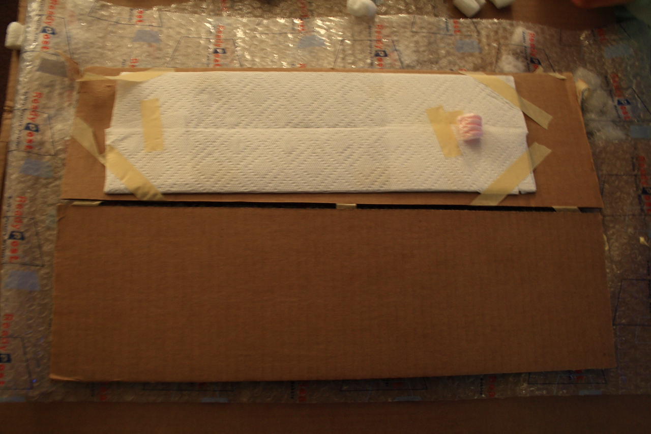
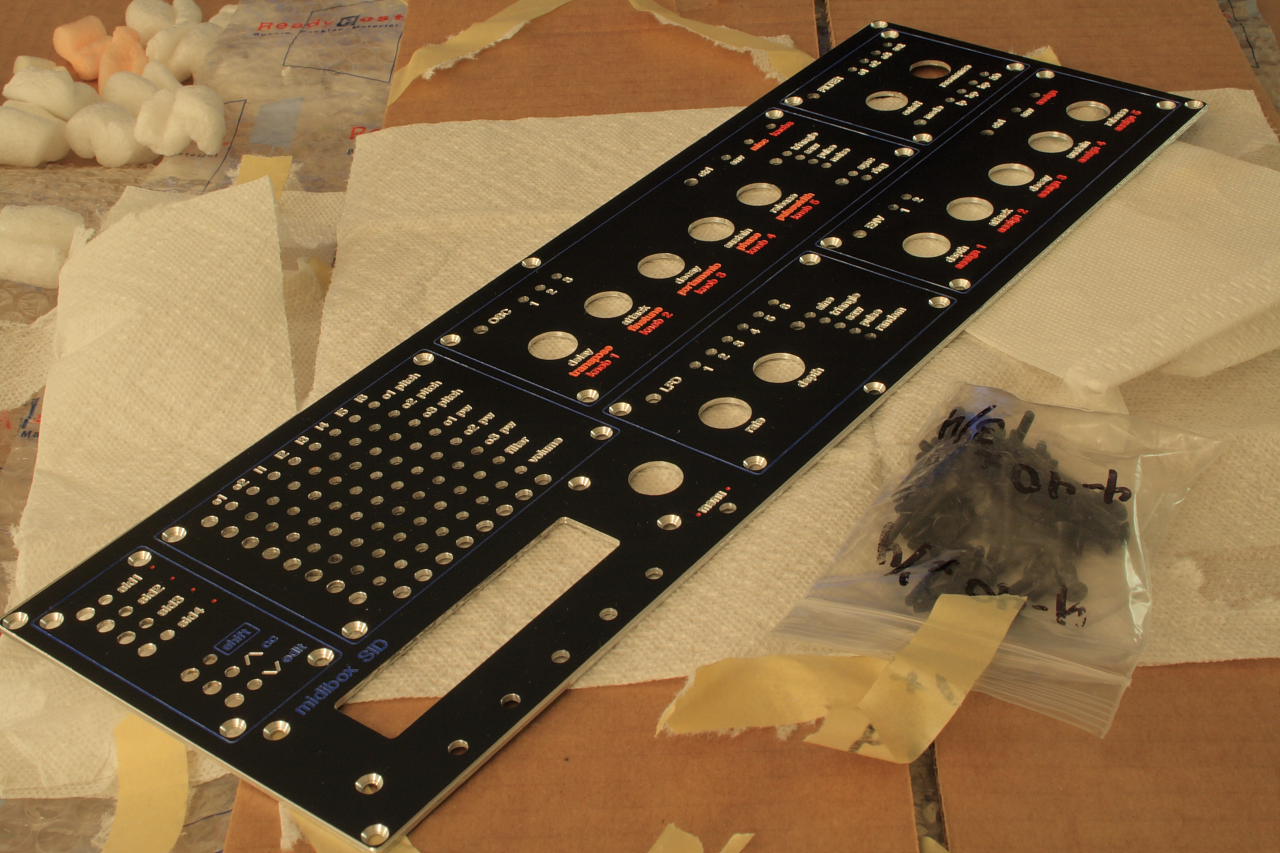
SID panel from Steve...

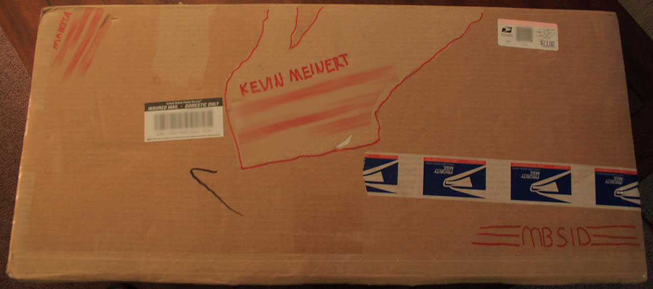
On the back is a message from Steve
I started adding a few control surface modules I had built against the panel printout I made from Front Panel Express. They fit perfectly. I'm using the bublewrap below to protect the panel front from scratches...

Added a few pieces to the panel...
Just 3 more sections to go for the front panel... Then I'll continue with the interior...
11.08.2007
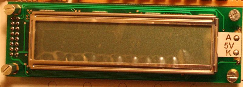
11-2am created the LCD module. this was tricky, I had to make an extention board that juts out from the LCD so I could mount a small sub-board onto it for the LCD menu buttons and encoder.

LCD section built
03.08.2008
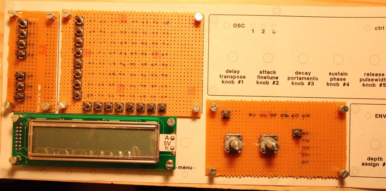
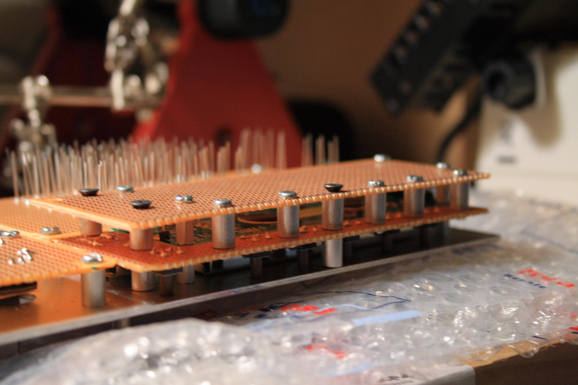
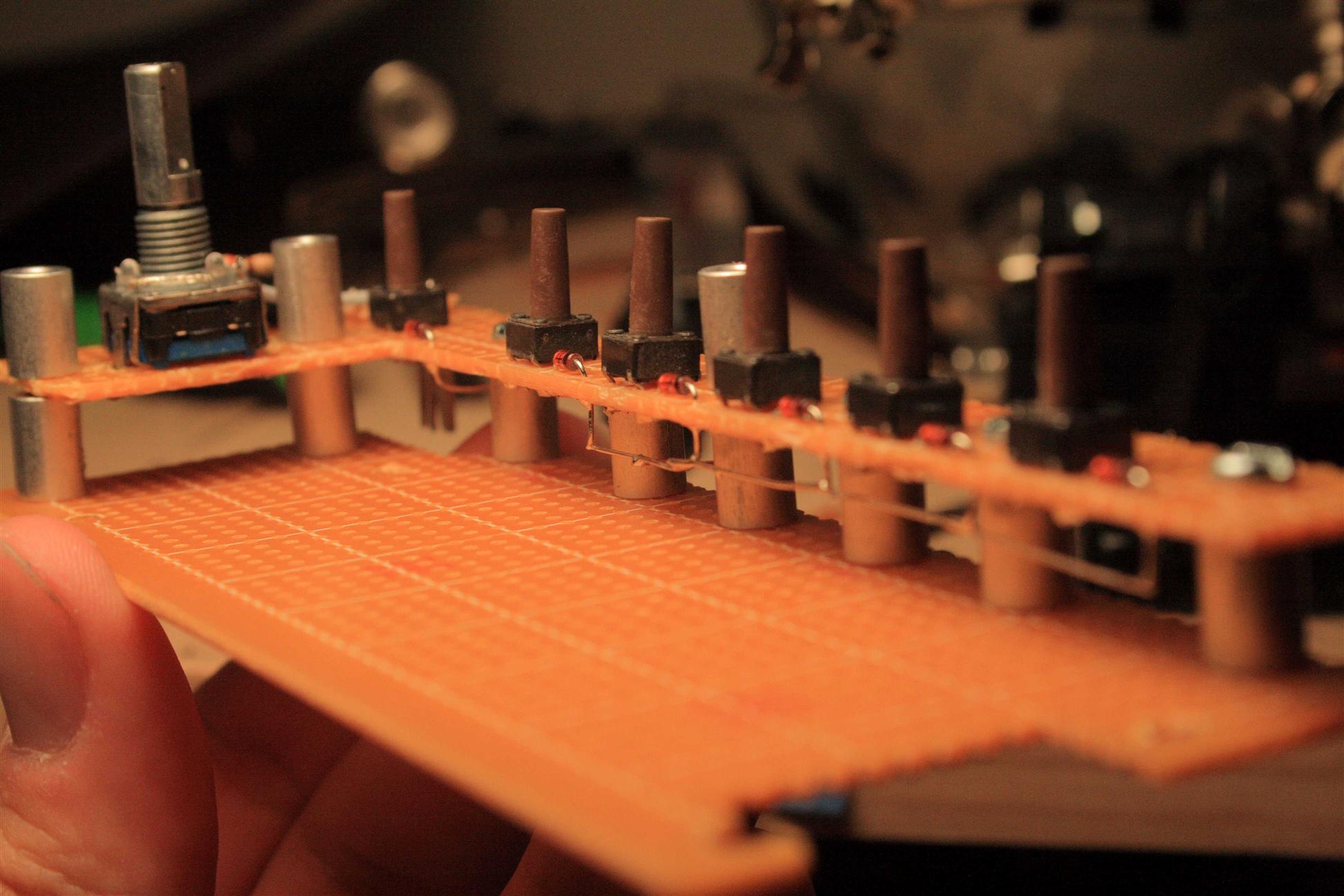
10-12:30midnight For the last few weekends I finished up the remaining sections of the control surface. Tonight I finished the layout. I left the widest section until the last, it was slightly tricky because I didn't have blank PCB that was long enough, so I used 2 fitted together. Because of it's length, I added a support in the middle as well. I do plan on doing LEDs behind the knobs, (lighted knobs), but for now I'm going to leave that work till the end.
Remaining control surface is built
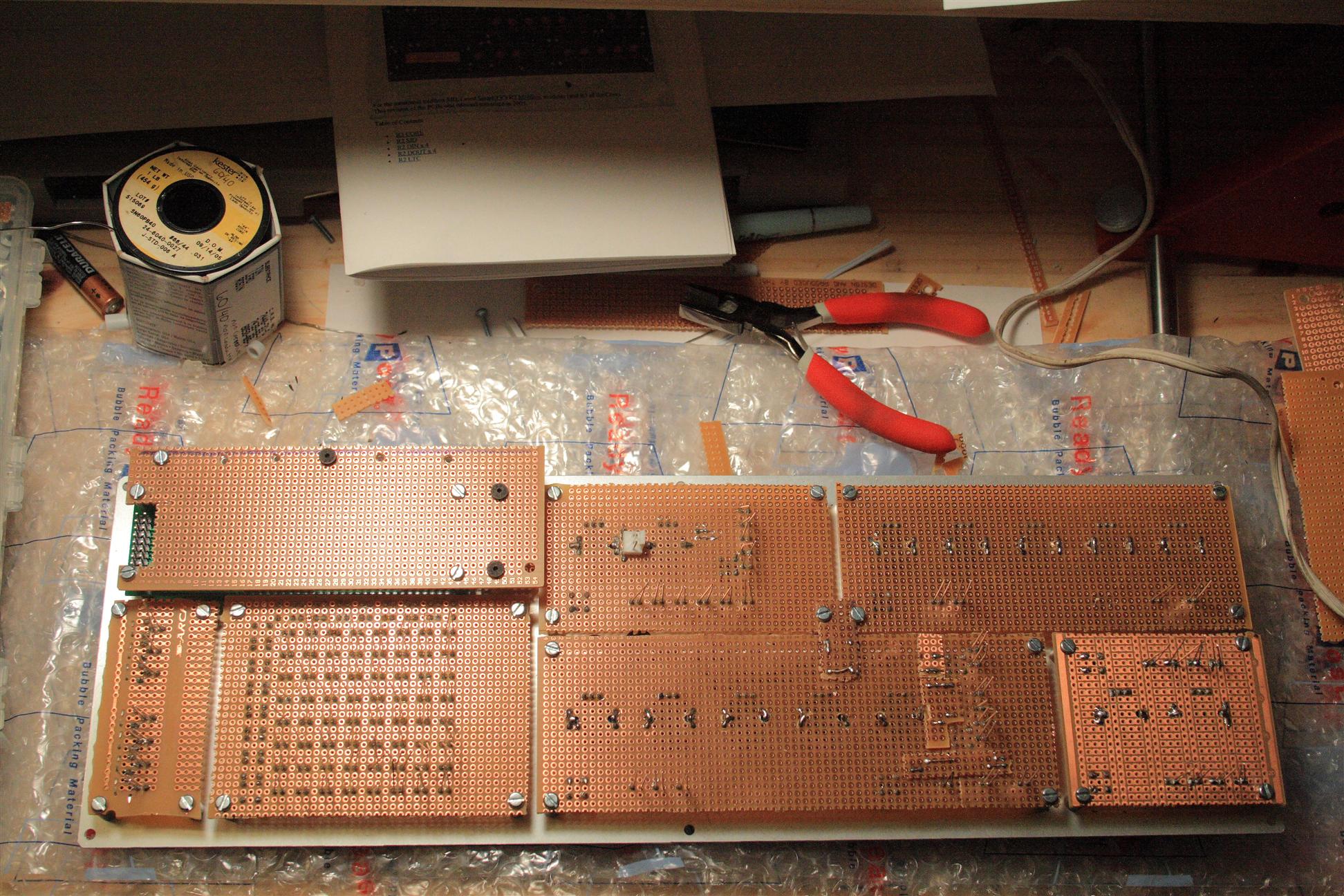
The back of the control surface (unwired)
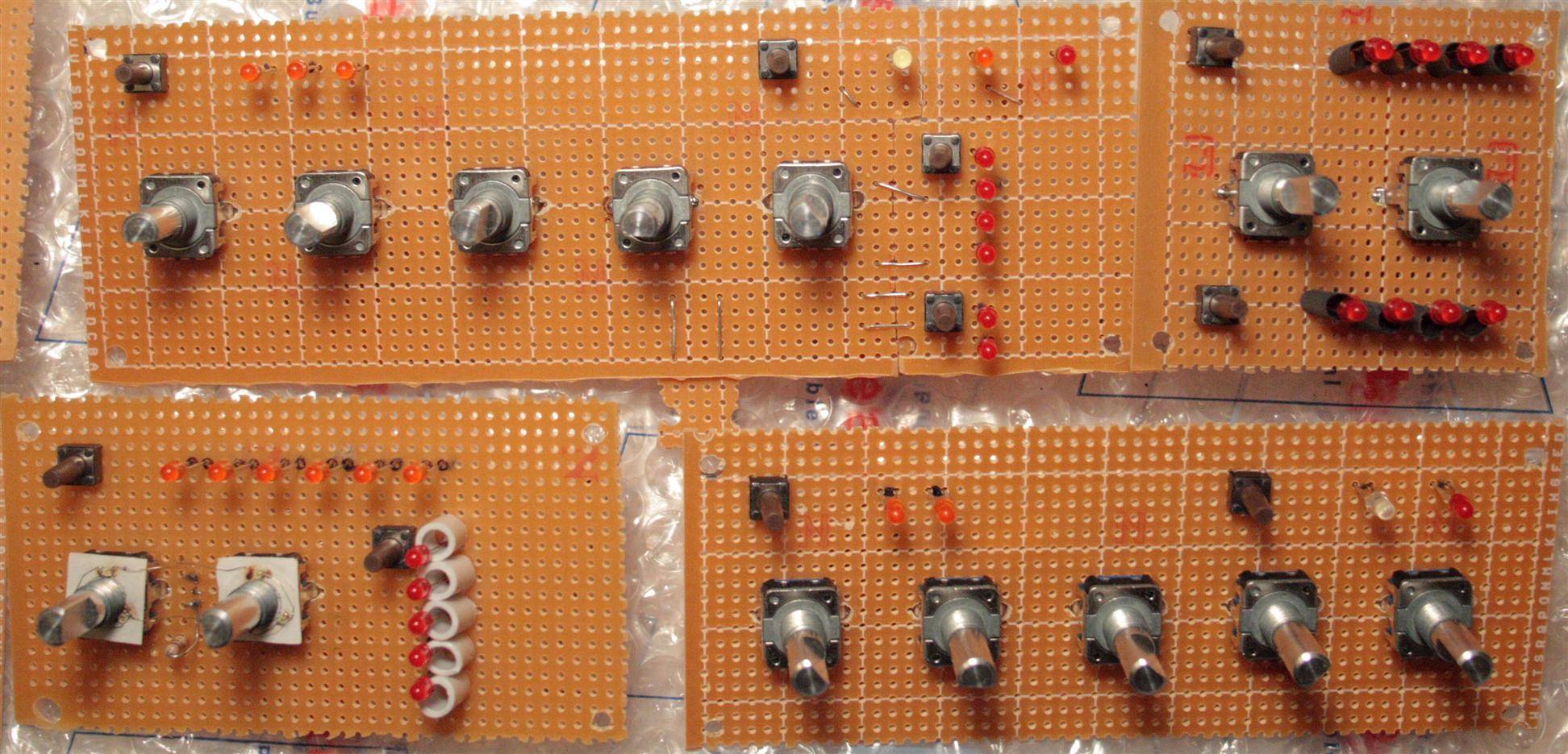
all control surface modules...
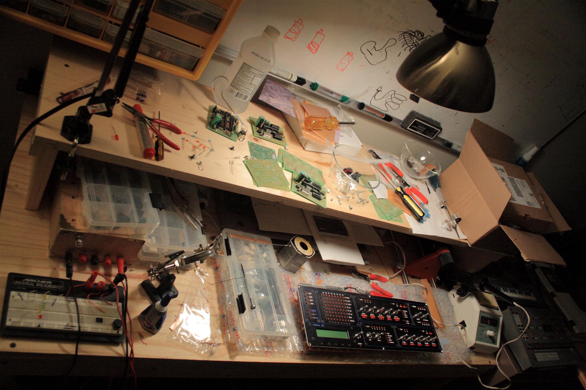
the workspace so far...
03.09.2008
8-10pm Tonight I cut the case so that the panel would fit. So exciting. This is the first time we get to see roughly what the midibox SID synth will look like... I started by laying the panel over top the empty c64 keyboard shell, and marking the 6 mounting holes where the panel would screw. Then I drew an inner border where I thought would be a good place to cut. Luckily this lined up pretty well with the existing hole (see pictures), so cutting was minimized.

Marking the holes and cutting lines on the c64 case
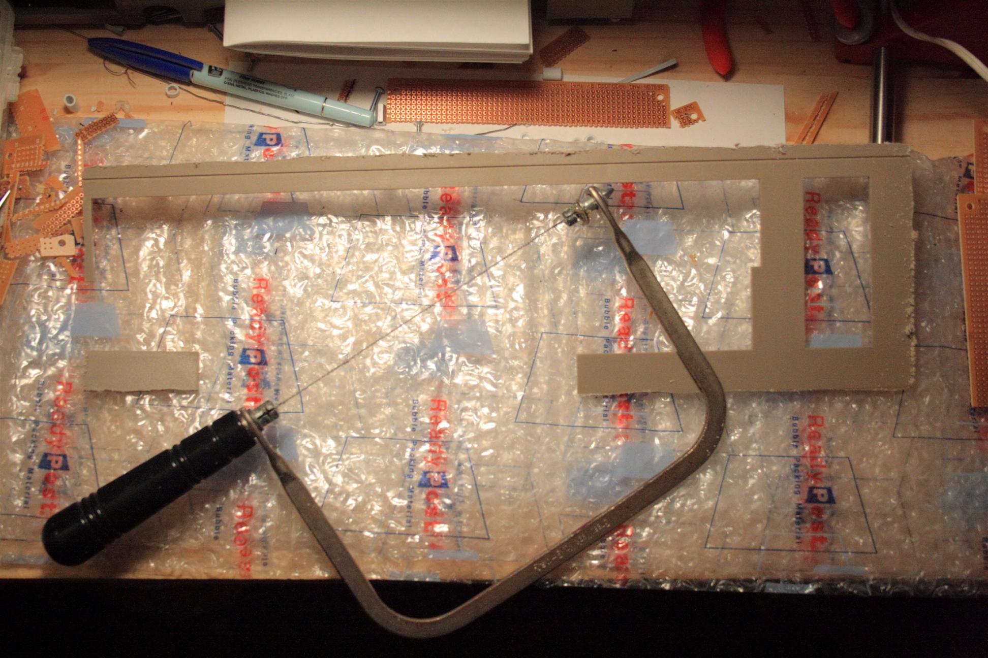

Case is cut... panel almost fits...
Make a little more room for some of the panel standoffs and menu buttons
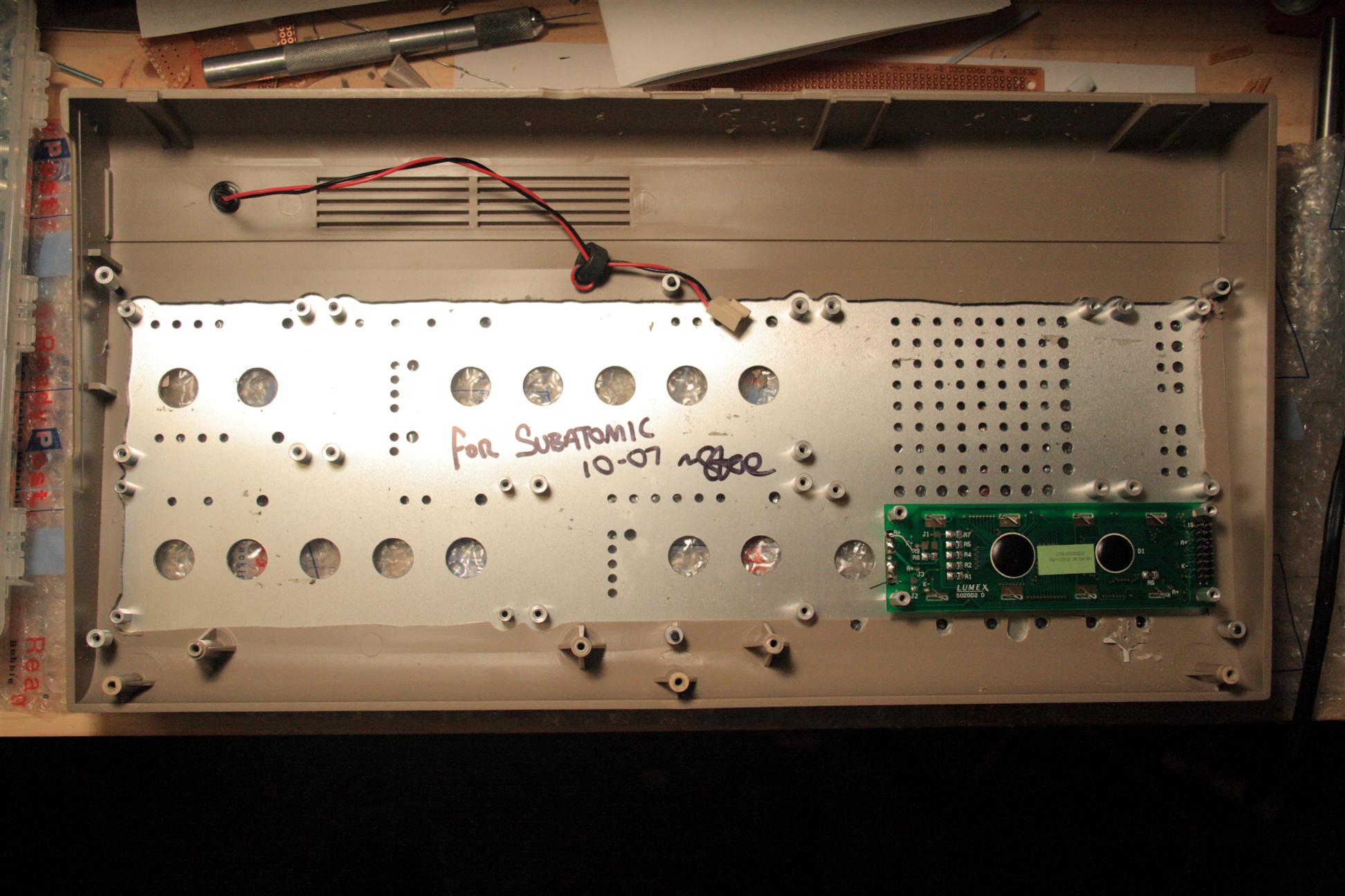
Test fit the panel onto the c64 case, looks good!
I finished by test fitting the panel onto the c64 case. I used standoffs as "nuts" behind the panel.
03.10.2008
7-8pm Paint. I started by masking all the important areas, like the c64 logo, power LED, serial number, and rubber feet. I then used Krylon Fusion Black (Satin) paint and did several light coats. Painting was fast, this stuff dries almost immediately, and keeping the coats light, no runs, all painted in under 1 hr.
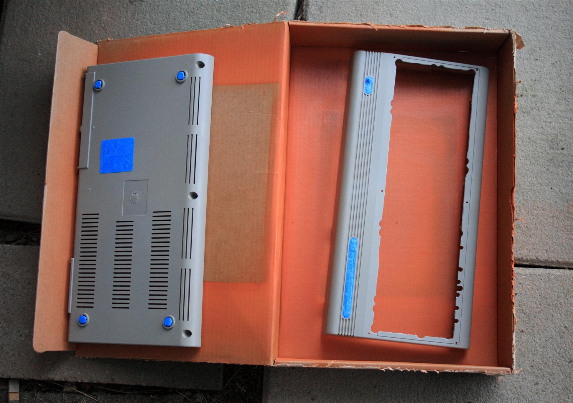
Masking the case, ready for painting


Black c64 case, freshly painted
with control surface
03.14.2008
10pm-1am Finish up PSU. I needed to add terminals for the bankstick ports (rs232 9-pin serial ports), and also added a terminal for unregulated 12VDC for the knob lighting, tapped off the point right before the 7809 regulator (suggested by Wilba from the midibox forums).
Added terminals for each serial port, and for unregulated 12VDC (knob lighting).
03.15.2008
7-9pm IO Panel. On the back of the c64 case, there's two empty holes where the computer used to present some IO ports. Tonight I filled one of those holes. What better place for 1/4" jacks and other audio stuff... I had an old piece of panel thickness aluminum laying around, and cut a piece to fit. Mounted there are 2 1/4" jacks, and a dimmer for the knob lighting. I also created the dimmer pot assembly tonight as well, using some pot from a radio grabbag with the brand name ISHKA on it (100k)...
New IO panel, and knob-light dimmer pot
03.16.2008
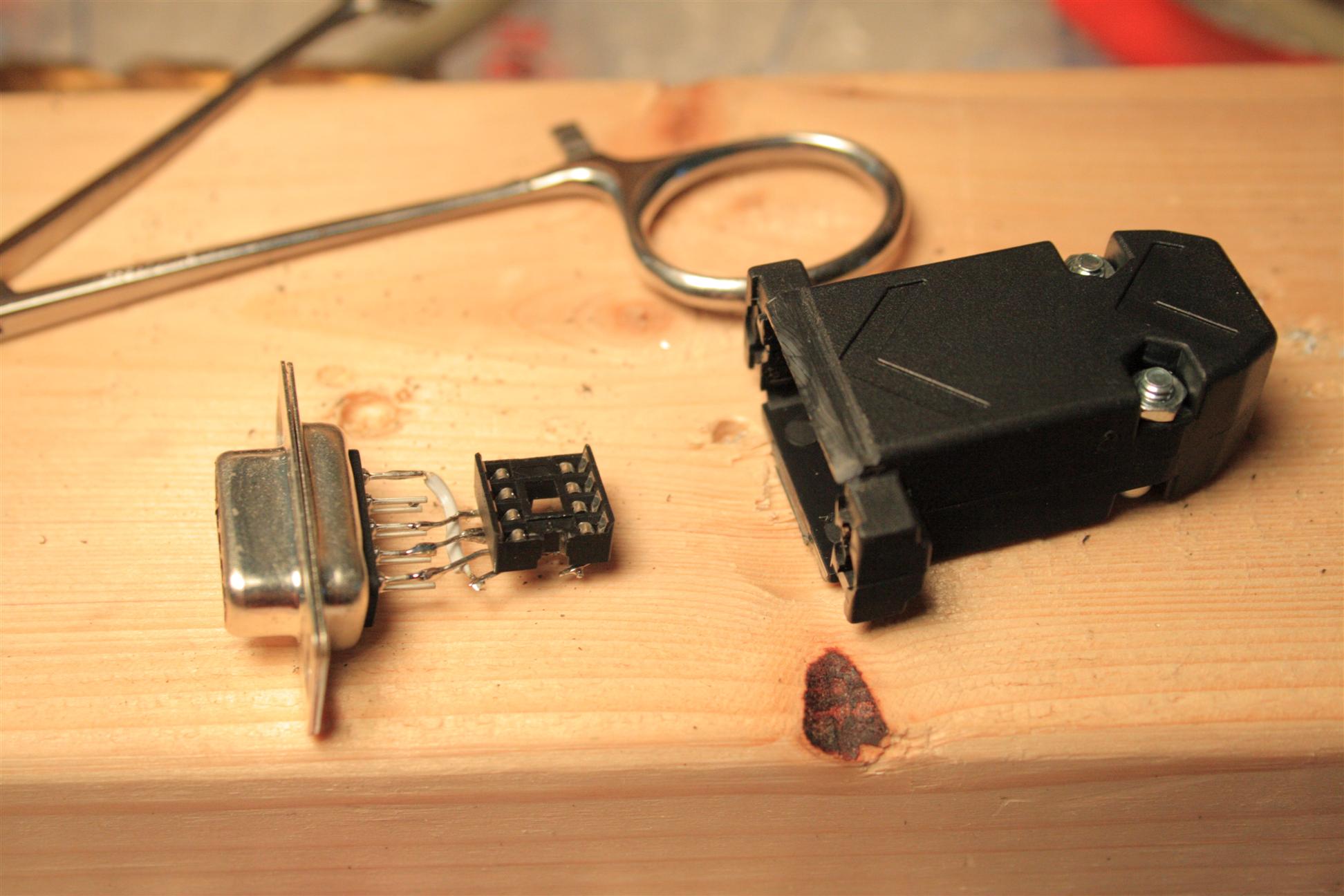
3-5pm Banksticks. These are the patch memory sticks (external, removable). Think USB sticks for the 80's... hahah. :) Anyway, I had some RS-232 housings I bought from somewhere (looks like digikey stuff, but I don't remember).
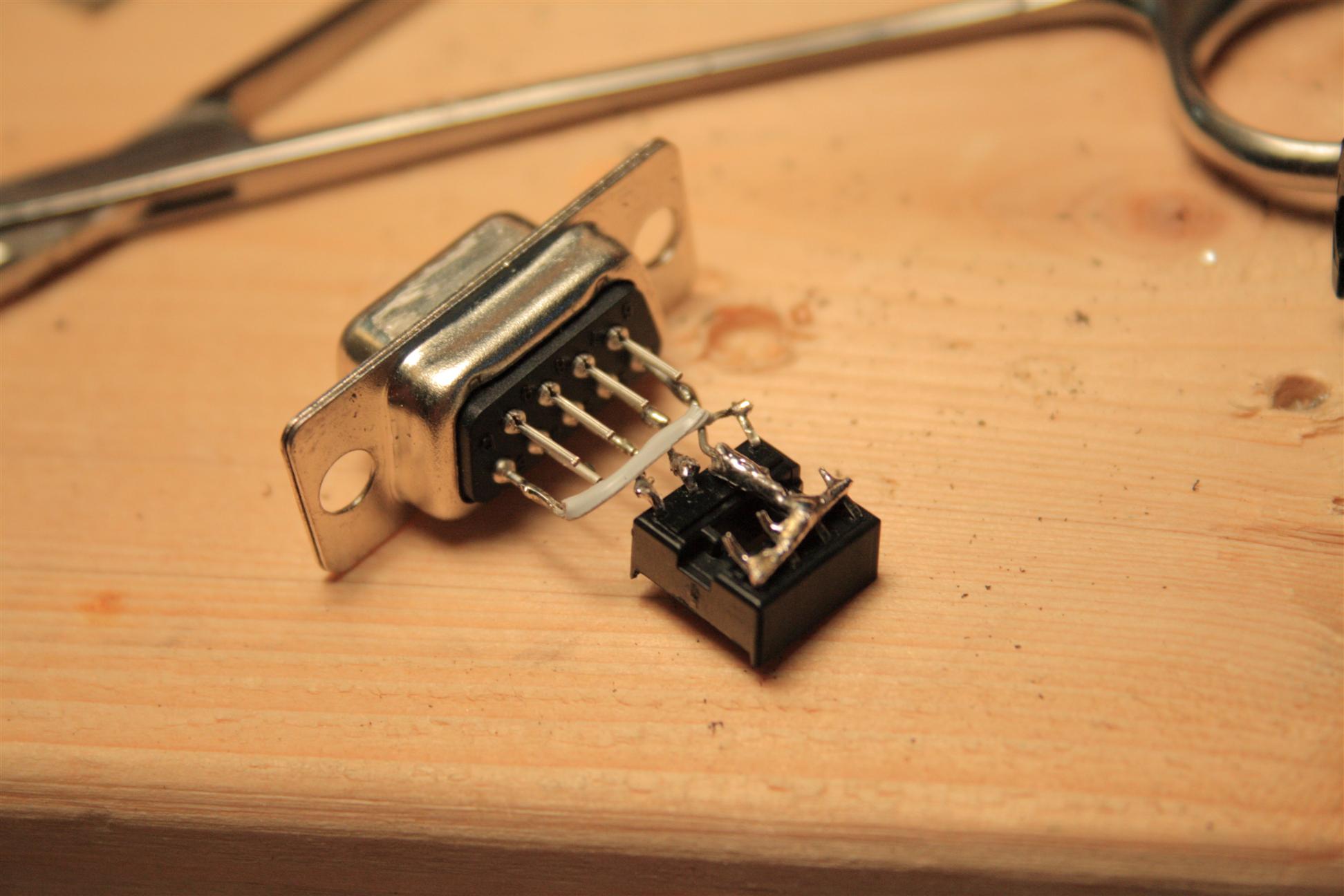
The sticks have an annoying piece of plastic that prevents them from fitting onto the c64 serial ports. So I had to do some modification using some 1/2" 4-40 type flathead machine screws and nuts, counter sinking the female 9-pin piece, and clipping off the offending piece of plastic. See pictures...
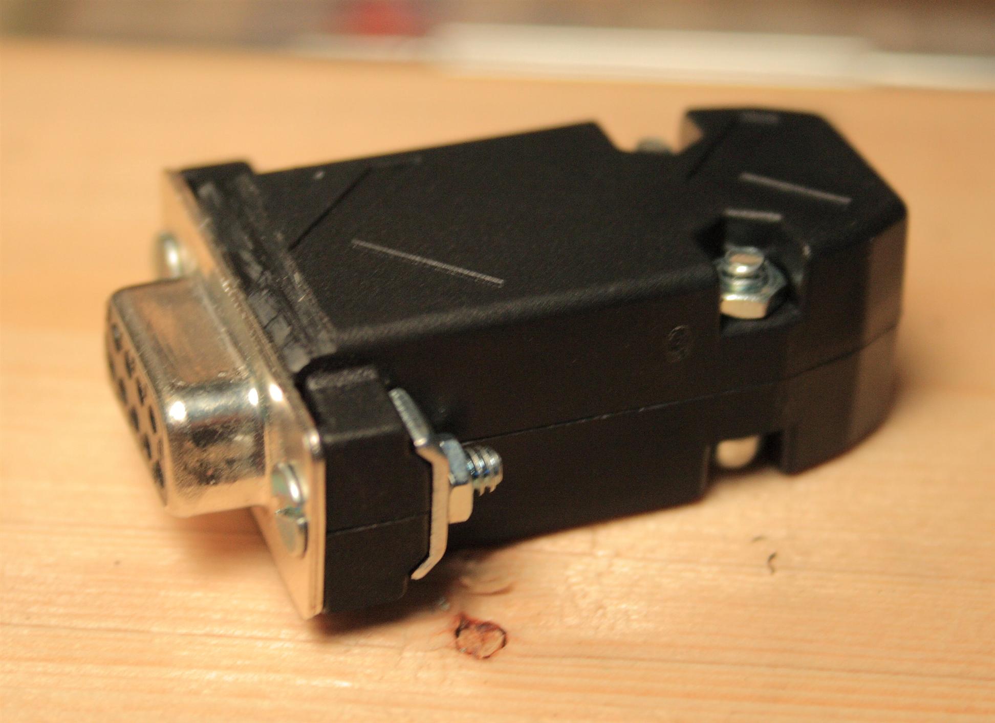
A finished bankstick for the midibox sid.

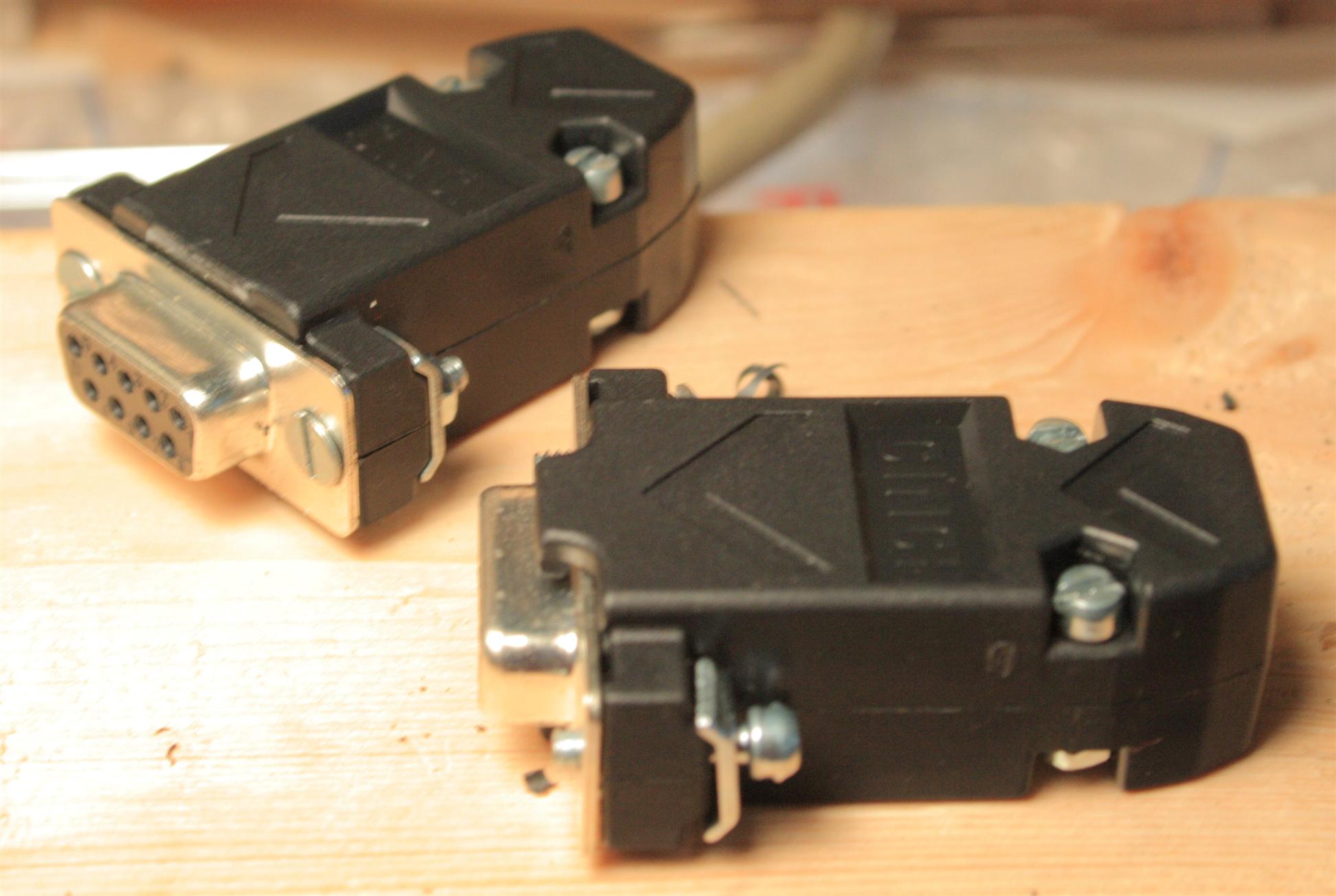
modifying the RS-232 housing to fit the c64 case serial ports.
before (right), and after (left)
stuffing the bankstick with an EEPROM chip
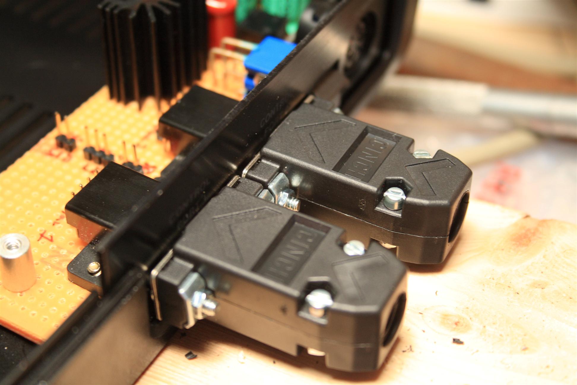
banksticks plugged into the c64 case
03.29.2008
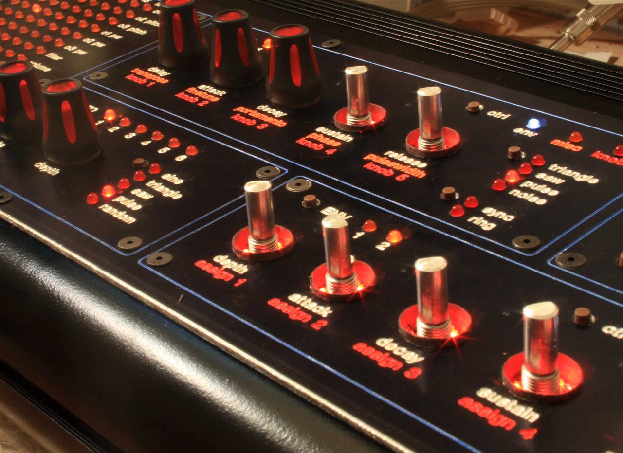
10:30-1:30am Finished Knob Lights. So I've been working on the knob light LEDs for the last couple weeks, completing a module (or a half a module) once every few nights. I used red "gullwing" style subminiature LEDs (thanks to Wilba of the Midibox forums for the LED tip, backlighting idea, as well as some other pointers regarding this feature!) from QT optoelectronics, which can be obtained from rockby.com.au #34421. Gullwing is the type where the connective leads come out the sides of the LED and then protrude up making for a non conductive base under the LED to glue to the knob.

QT optoelectronics - subminiature T-3/4 (1.9mm) LED
Used superglue to attach 3 of the LEDs onto each knob. Added a polarized header (power plug) to each controlsurface module. And added sockets for the resistors (1 resistor per knob), so I can adjust them as needed: it's a real pain in the ass to unsolder anything next to these miniature LEDs, since they're so small. Each LED triple was wired in series along with one resistor socket, then all triples were wired in parallel with each other onto the 12V line.

Wiring the control surface knob back-lighting...
Looking down from the top
Total build time for the LED knob lights breaks down approximately like this, (times given are per module): 30 minutes for sockets and power header, 4-20 minutes to glue LEDs to knobs, 45-75 minutes for wiring LEDs. Obviously the 5-knob module took longer than the 1-knob module. Probably 45 minutes for the 1-knob module, 1.5hr each for the 2-knob modules, and 2hrs each for the 5-knob modules.
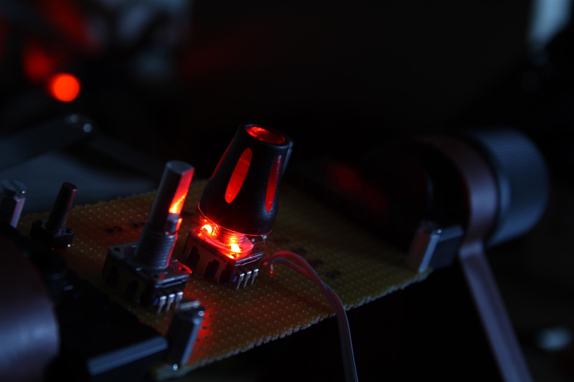
Fire!
A lot of work, but it was really cool to turn them all on and see them blazing away... Already, I can see I should add a light blocker (black paper) around each knob base, and let the paper ring protrude maybe 2mm above the surface so the underlighting isn't directly visible to the eye. I went with 330ohm resistors, with a 12V supply connecting each module in parallel. The 12V supply runs through a dimmer pot first, which is mounted on the back panel (see earlier section). I tap the 12V from the unregulated section right before the 7809, but after the rectifier (see "optimized PSU").
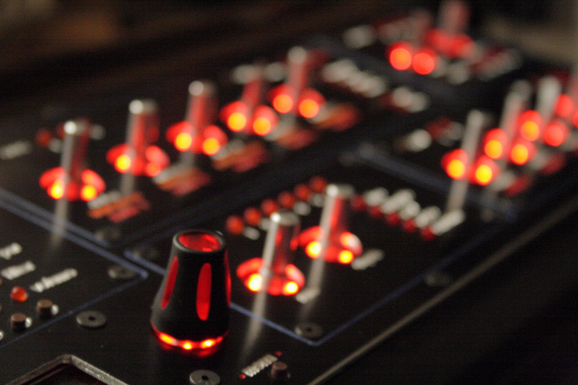
Lit knob. Naked sockets

Entire surface...
03.29.2008
--- So, I decided to do something pretty different. In the last few years while I was basically sitting on the MB modules, not building them, (to be fair i was busy, building other synths and crunching the day job on SWTFU), a guy named Wilba (of the midibox forums) has designed an all-in-one PCB, called the mb6582.
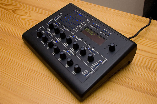
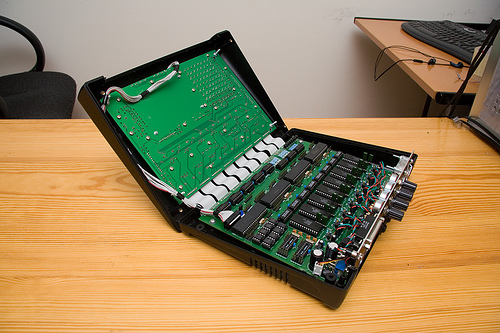
Wilba's mb-6582
I've decided to scrap the unfinished SID/CORE/DIN/DOUT modules in favor of building this all-in-one mb6582 "base PCB". The mb6582 is going to be far easier to build (no wiring between sections!), supports 8 SID chips, and is configured for the same control surface that I just built. What's more, Wilba's also doing a group order of 6582 SID chips, "old/new" stock. I'm going to use these chips instead of my 6581's. Through Wilba, I'm able to get 8 6582s. Why new SID chips? Well, it's rumored that the 6581s often don't work fully, also, the new PCB supports 8, and I saw a youtube demo of TK's MBSID in bassline mode using 6582's and I liked the sound, so why not. And... SmashTV is doing a group order of all the parts needed for the mb6582 base pcb. This is getting very close to being a "kit"... :) Very cool... With this little "boost" in productivity, I hope to be done real soon now...
05.1.2008
9:30-10:30pm Looking over the mb6582 docs, I noticed they didn't have the encoder connection diagram so I took a little time to figure it out tonight. Pretty simple, but I like to have this crap figured out ahead of time, makes the soldering less error prone.
encoder diagram
05.2.2008
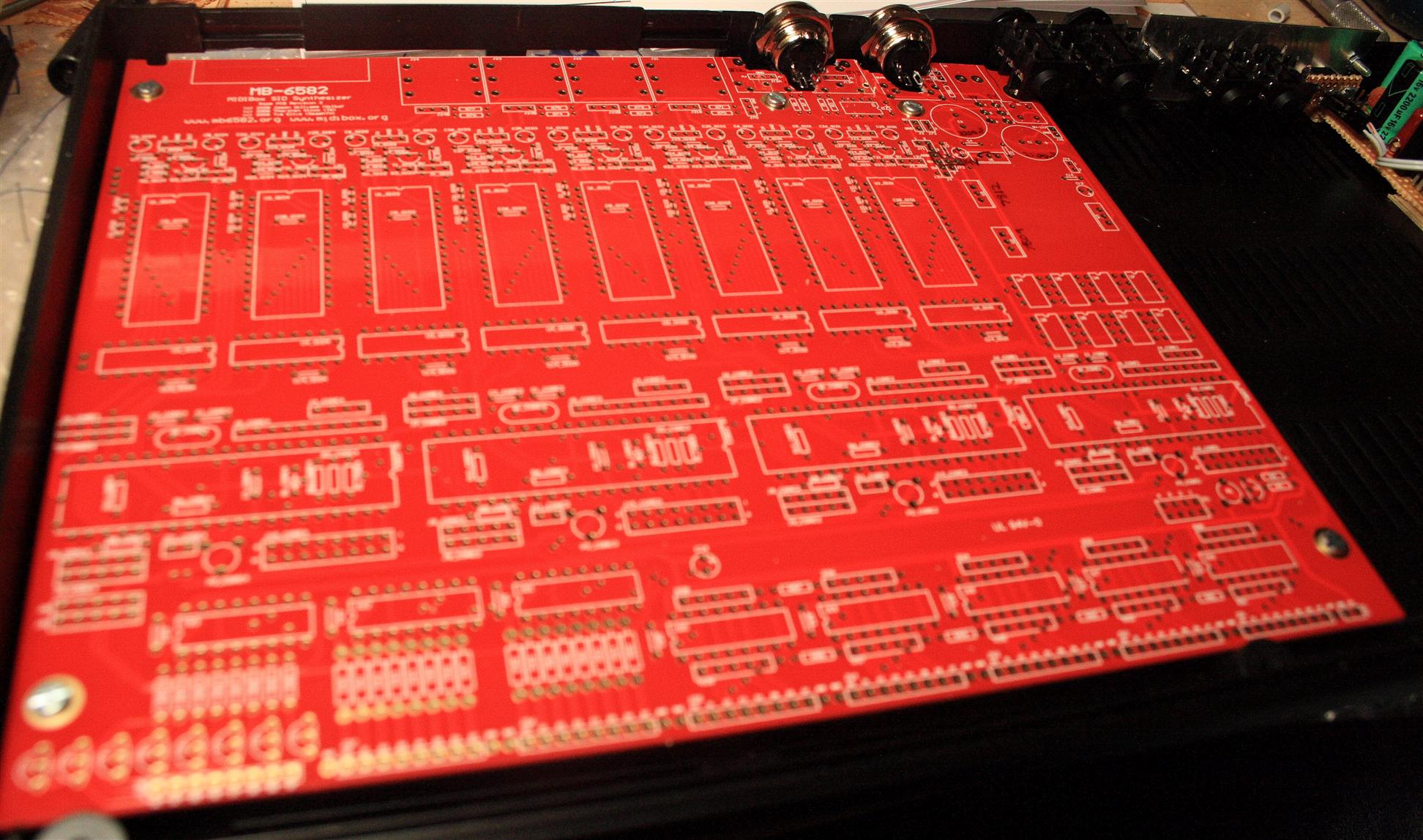
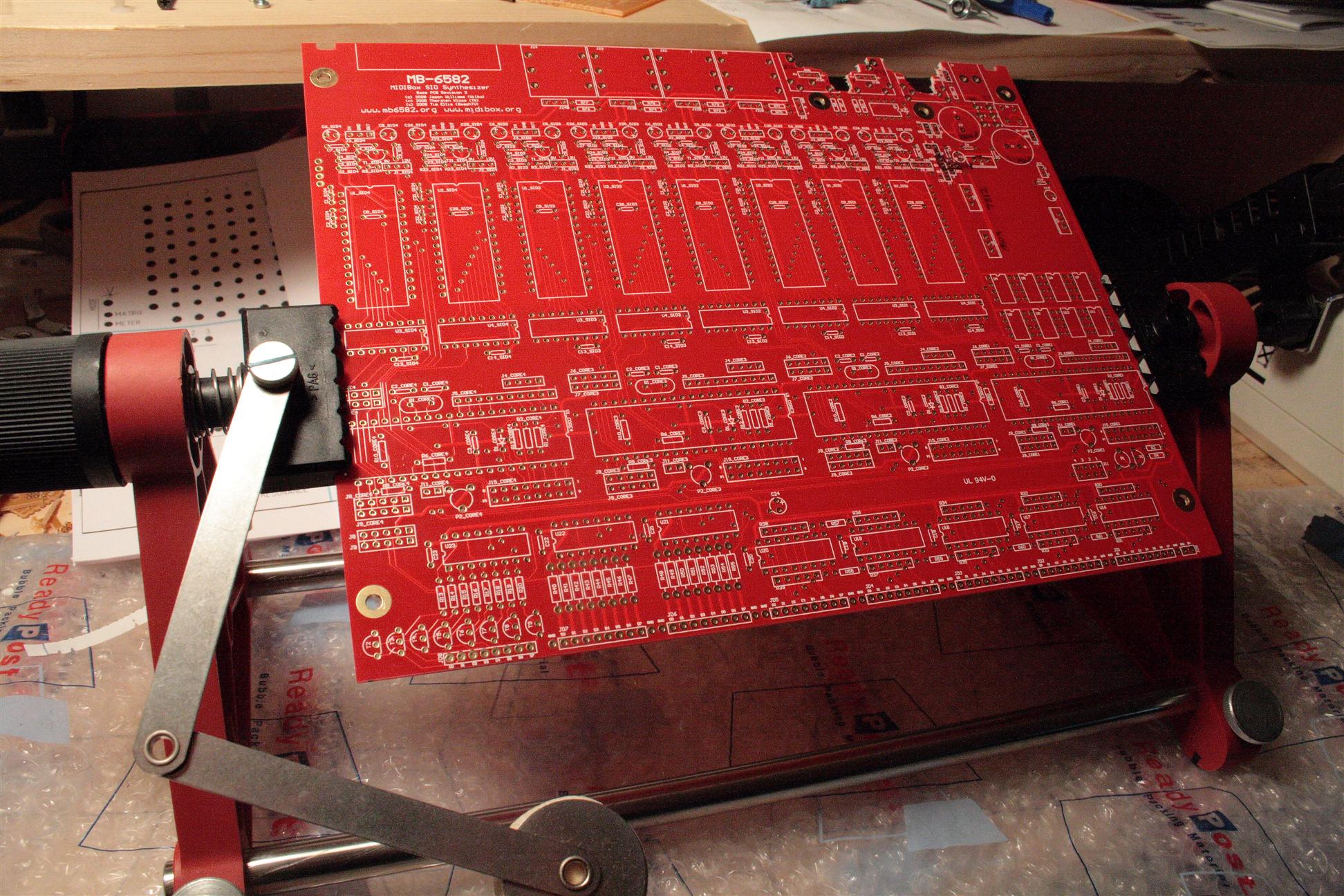
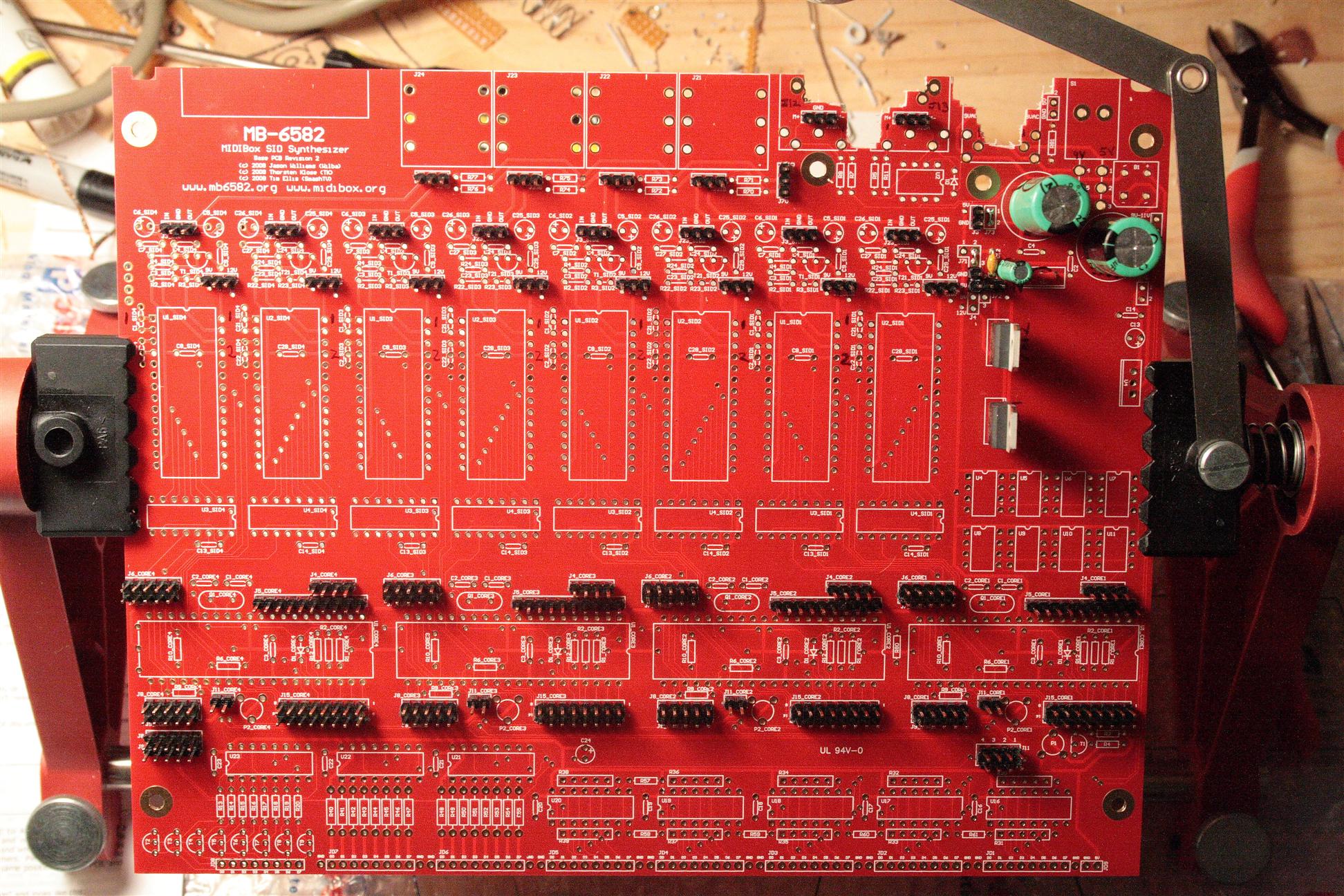
--- The MB6582 has arrived. While I was crunching away at work Friday, the SmashTV mb6582 base parts + base and control surface PCBs arrived, along with 8 6582 SID chips from Wilba. Of course, coming home at 1am, I was oblivious, and then woke up to find them the next morning...


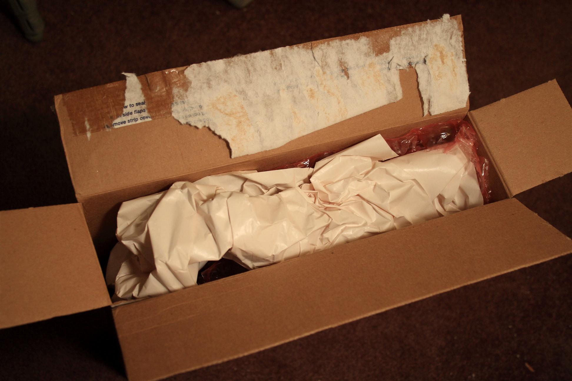
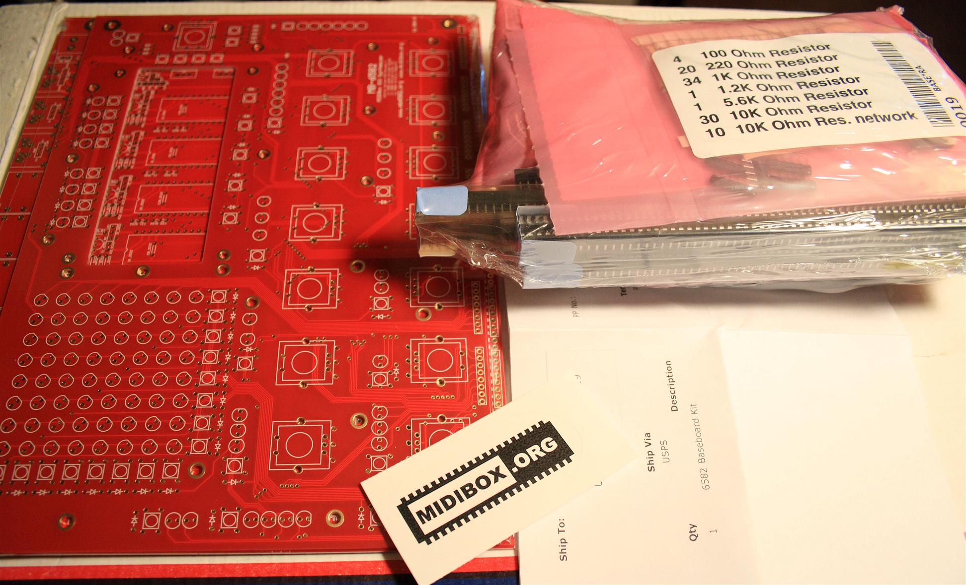
mb6582 parts arrived
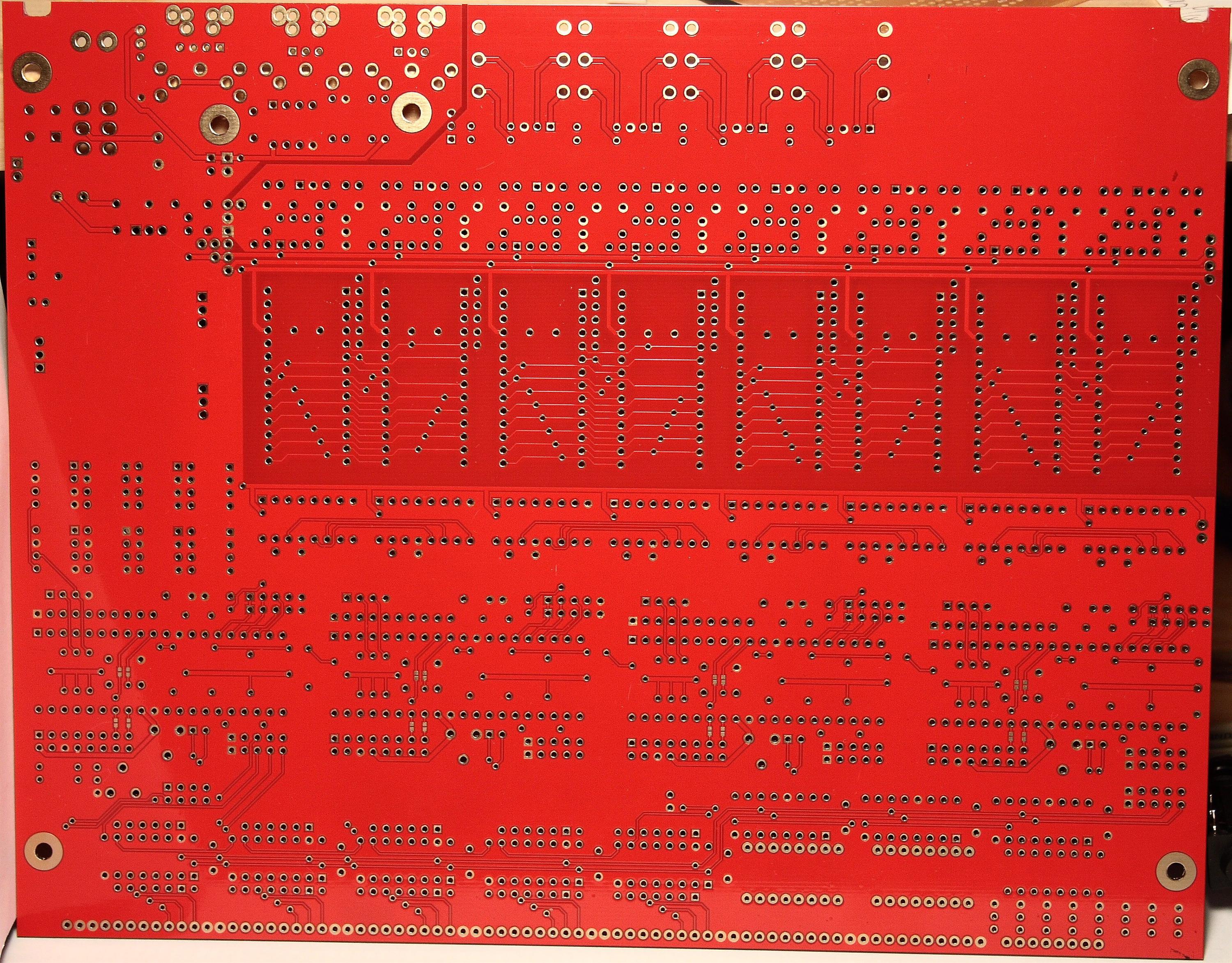
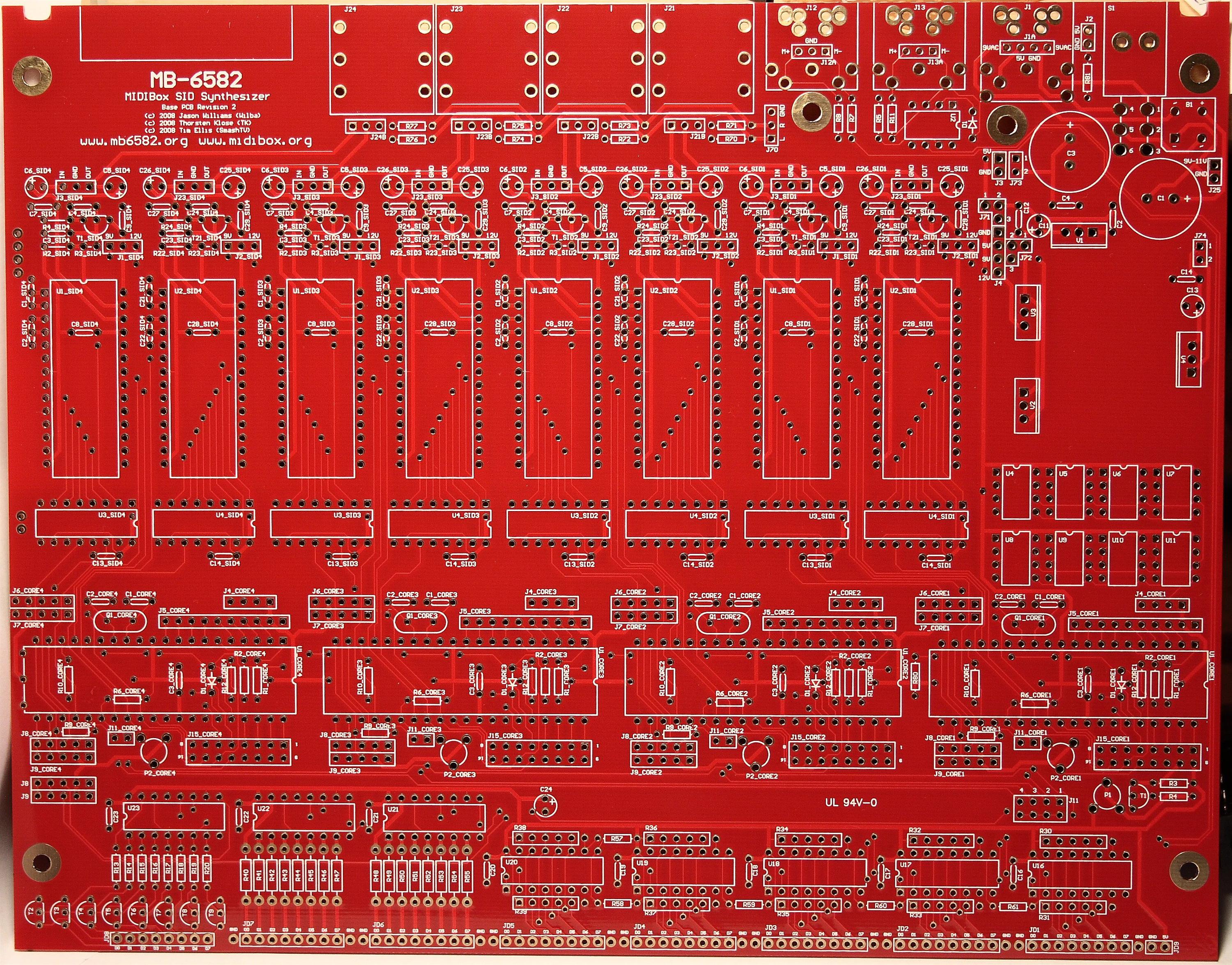
mb6582 base PCB (front/back)
05.3.2008
9:30-10:30pm Printed out manuals for the mb6582, thanks to wilba for providing such a concise, easy to follow guide! This is far easier than the sprawling texts of the MBHP modules. (much helped by having the PCB all-in-one, holy straightforward batman.)
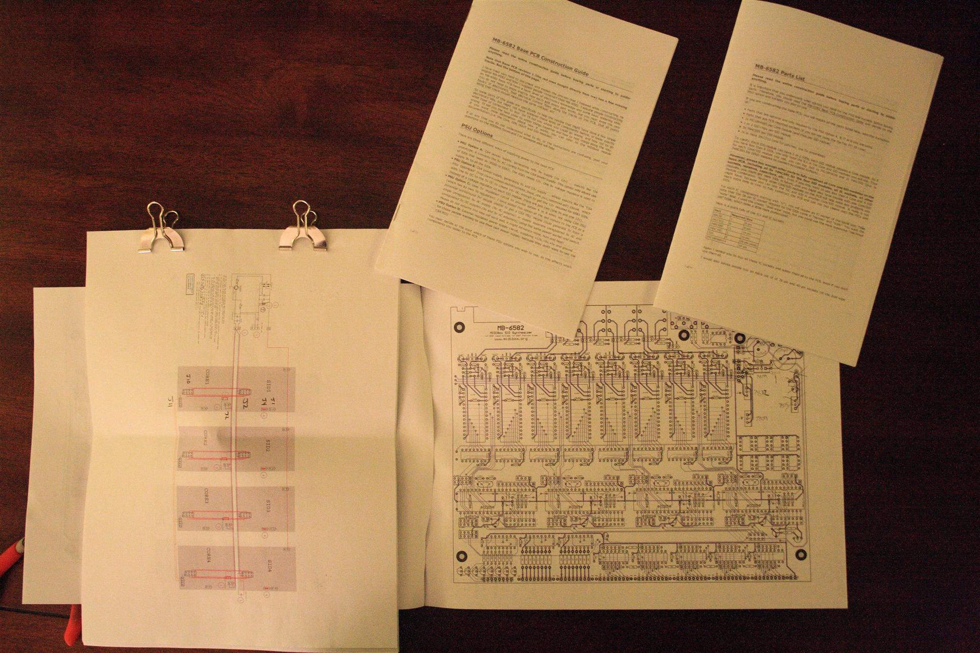
printed manuals needed for construction of the base mb6582 PCB
05.12.2008
7:30-8:30am
Vacation! (2 wks, yay!)
Reading through the mb6582 docs, the first step is to figure out how to power the board. The docs present 4 options (A-D) for PSU, unfortunately I already have the "optimized PSU" built, and none of the 4 options tell how to connect an existing optimized PSU to the mb6582 pcb. The optimized PSU supplies only GND, 5V, and 14V.
So, I took some time and figured out a new option: "PSU Option E" which is useful for people who already built the optimized PSU and want to continue to use it with the mb6582 PCBs...
I want to use my existing PSU because it's already built. Of course, I could have just as easily built option B, which would have then supplied GND/5v/9v/12v using components soldered onto the mb6582 PCB...
Anyway, here's my "PSU Option E":
For reference: here's the Optimized PSU (which outputs GND/5V/14V) recommended for use with a V2 midibox SID (what we're building).
How to connect the optimized PSU directly to the mb6582 base PCB:
Connect 14V to Pin1 of J72 *
Connect 5V to J4           *
Connect GND to J4          *
Connect C1 and C3          ****

Jumper J71 pins 2&3        ***
Jumper J72 pins 1&2
Jumper J73 pins 1&2        ****

Solder in V2 V3 C11** C12**

* This results in an "L" shaped power header on the mb6582 base PCB... spanning J4 and J72
**  C11 and C12 are still needed because the optimized PSU diagram do not have them...
***  put C11 and C12 between ground and 14V  (see MidiBoxSID step A PSU)
**** extra filtering can't hurt, can probably skip J73/C3...
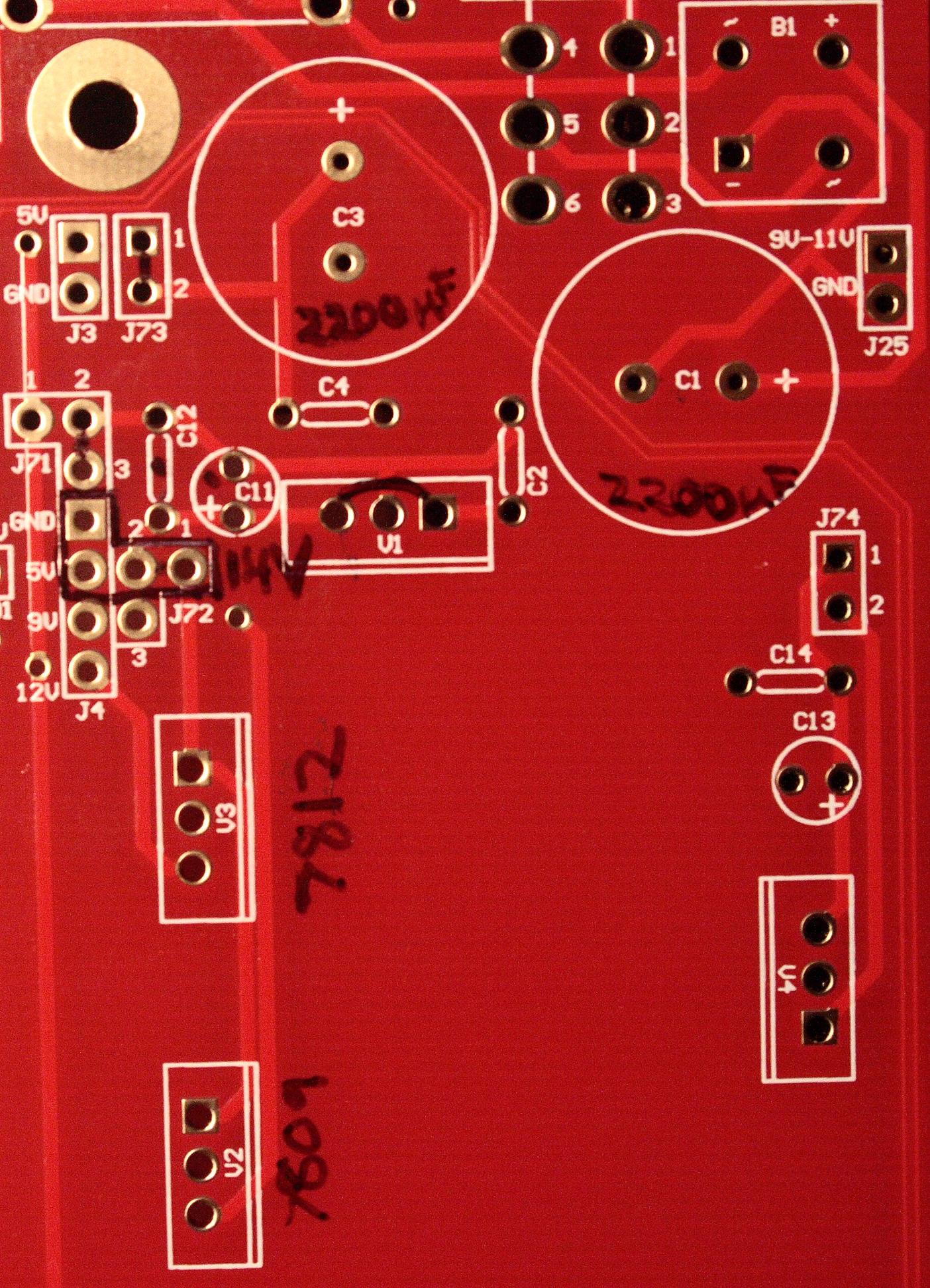
marked up the PCB for power connection...
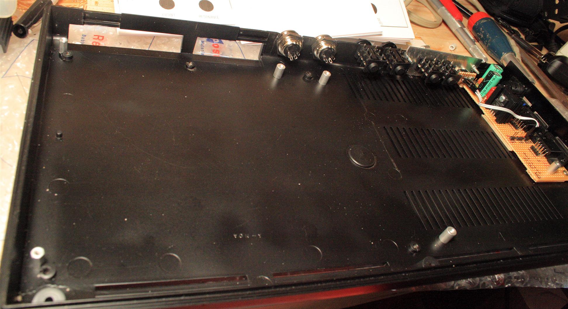
8:30am I next modified the PCB (cut huge pieces out of it) to make it fit the C64 case. (nooooooo!) It's not that bad... read on.
Remember I wanted to have midi jacks panel mounted to the back of the C64 case without cutting any new holes in the case. My goal is to keep the C64 case as original as possible, so instead of moving the MIDI jacks, I'm going to instead cut some holes into the mb6582 base PCB. And for this I use the nibbler tool...
Notice I left the headers for the MIDI jacks intact so we can still make a clean connection to the PCB from the panel-mounted MIDI jacks.
I have no need for the power jack, so I completely cut that out.
PCB doesn't fit with the MIDI jacks in the way...
...so we cut the PCB to fit
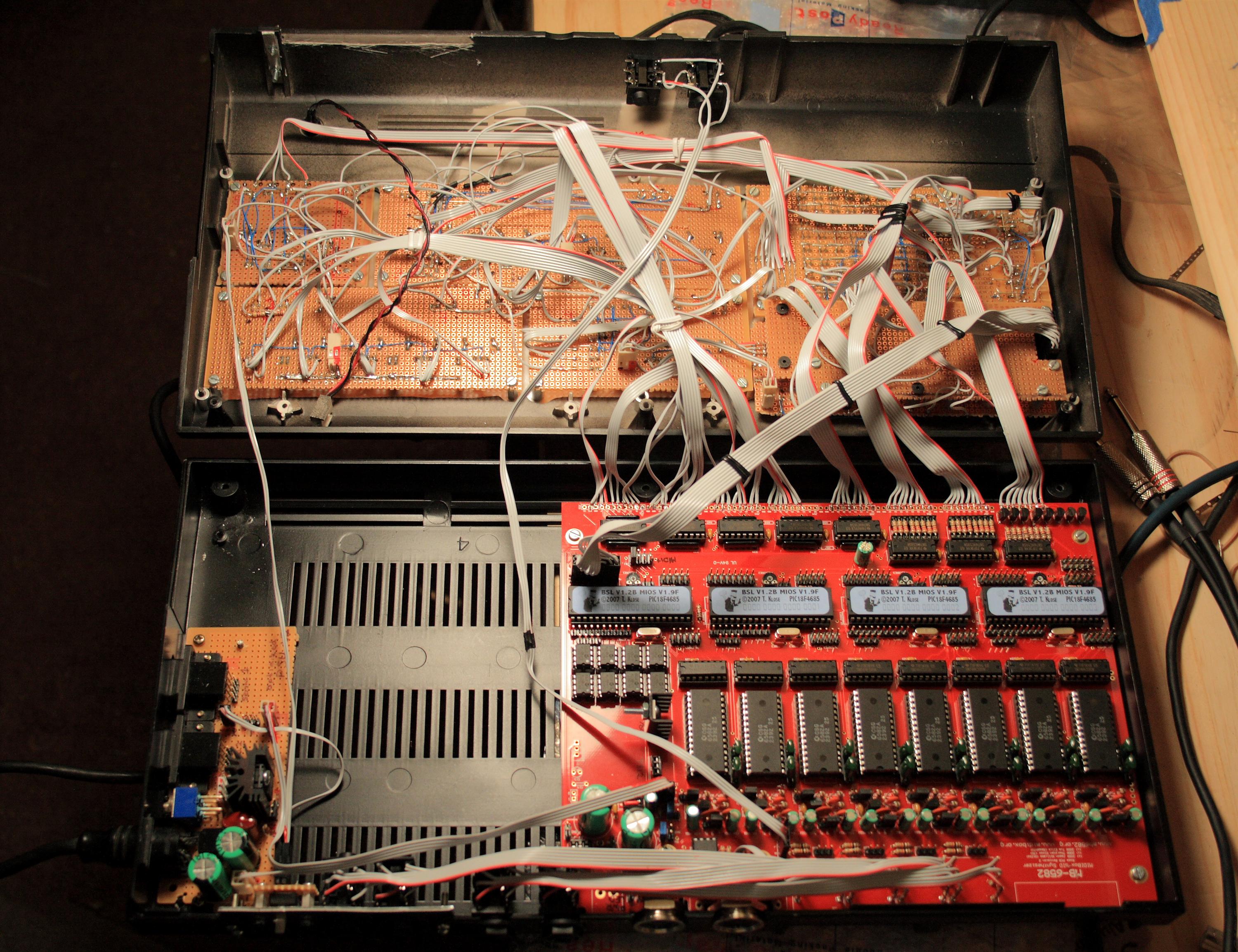
9-9:30am Next I mounted the PCB into the c64 case using aluminum standoffs.
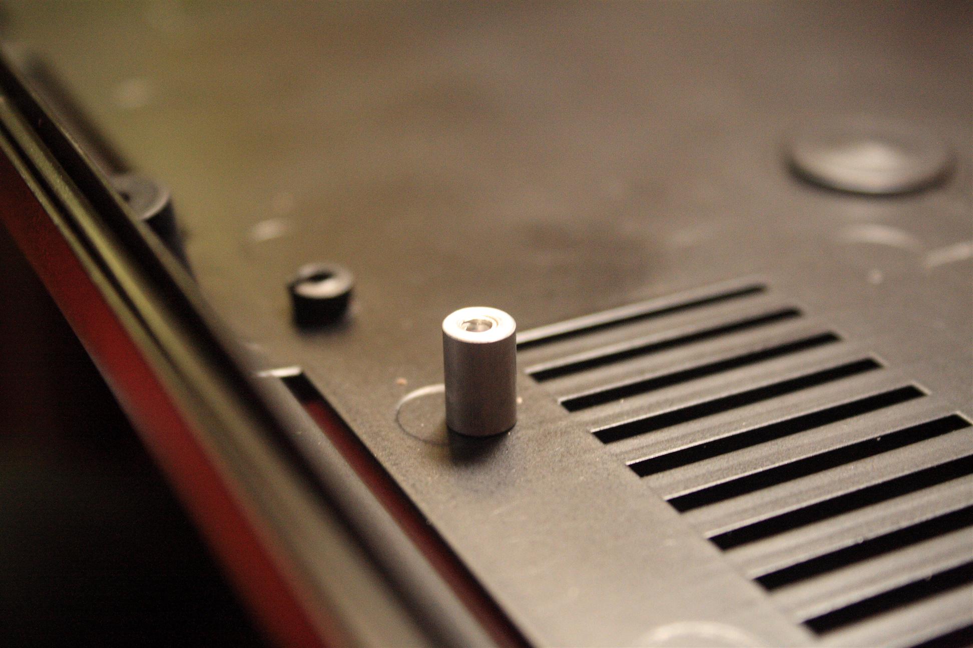
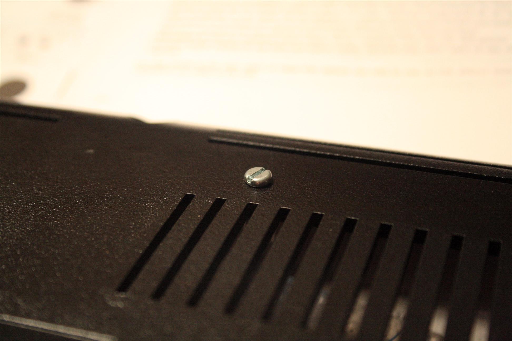
Aluminum standoff, mounted (top/bottom view)
mb6582 base PCB mounted in C64 case
Now that we have a home for the PCB in the C64 case, The PCB is ready for stuffing!
I like to have everything mountable in the case before moving ahead, that way, if I need to test things out, it's all ready to go...
Ready to stuff components...
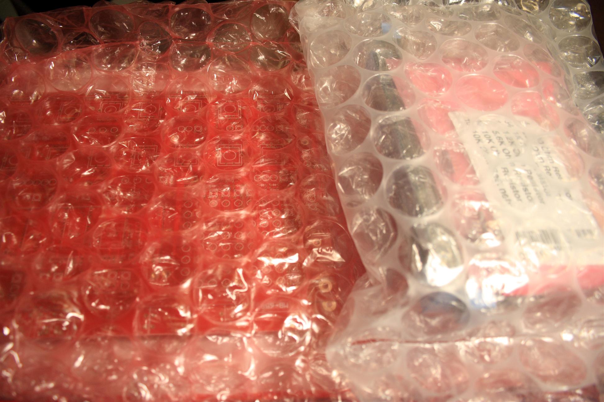
10-11:45am Next I opened and sorted the "MB6582 base PCB parts kit" that I recieved from SmashTV
Having the parts laid out makes them easy to inventory, test, and locate while building.

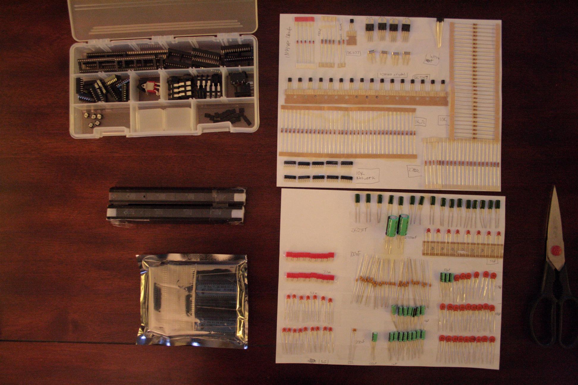
Sorting parts (before/after)
Next, I cut 8 sockets for the SID caps... So they'd be ready to go when I get to the SID section later...
The mb6582 docs recommend to socket the caps (C1/2/21/22) for each SID chip, in case you want to change the type of SID chip used. The 6581 needs a different capacitor than the 6582...
The recommended sockets are the machine pin type, but I don't have any, hopefully these will work just fine:
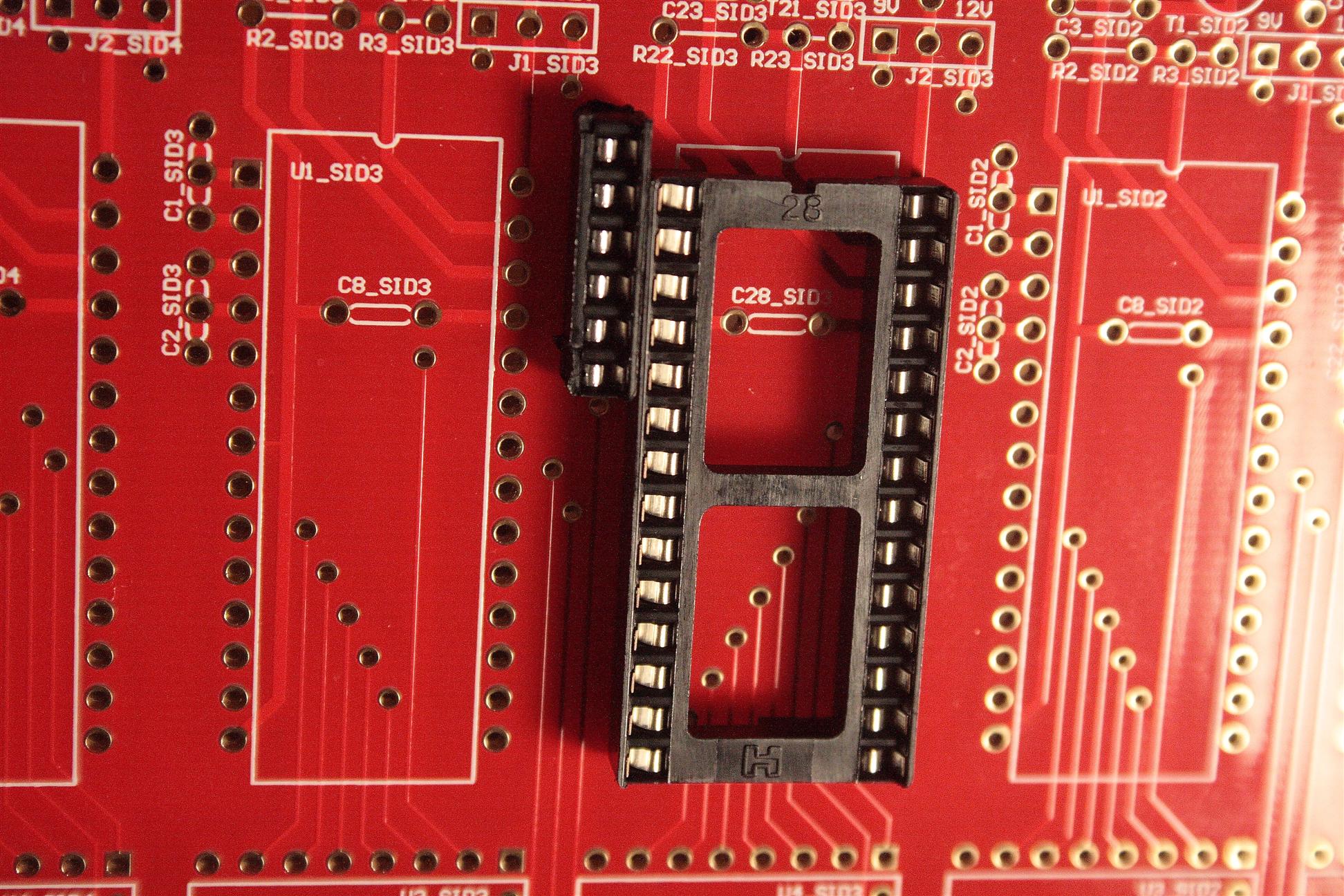
Capacitor socket for the SID chip.
05.13.2008
10:30am-11am Got a question this morning from moogah about what the MIDI jacks are that I have used. I'll copy the info here so everyone can find it...
I'm using this MIDI jack in the mbSID:
Digikey CP-1235-ND (CUI SD-50LS)
Here's the one I used on the 9090, it's somewhat similar:
Mouser 164-2522 (Deltron 651-0500)
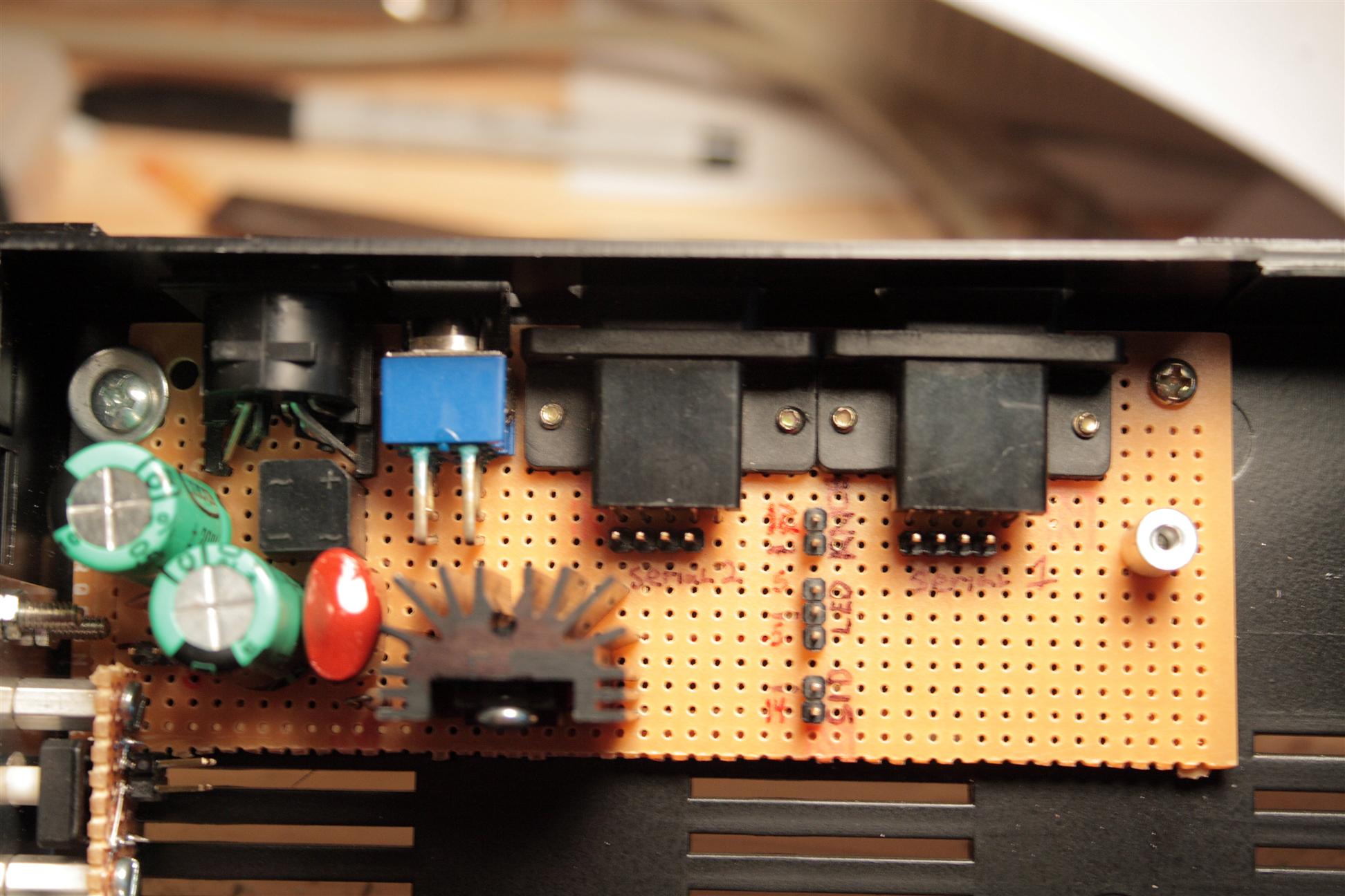
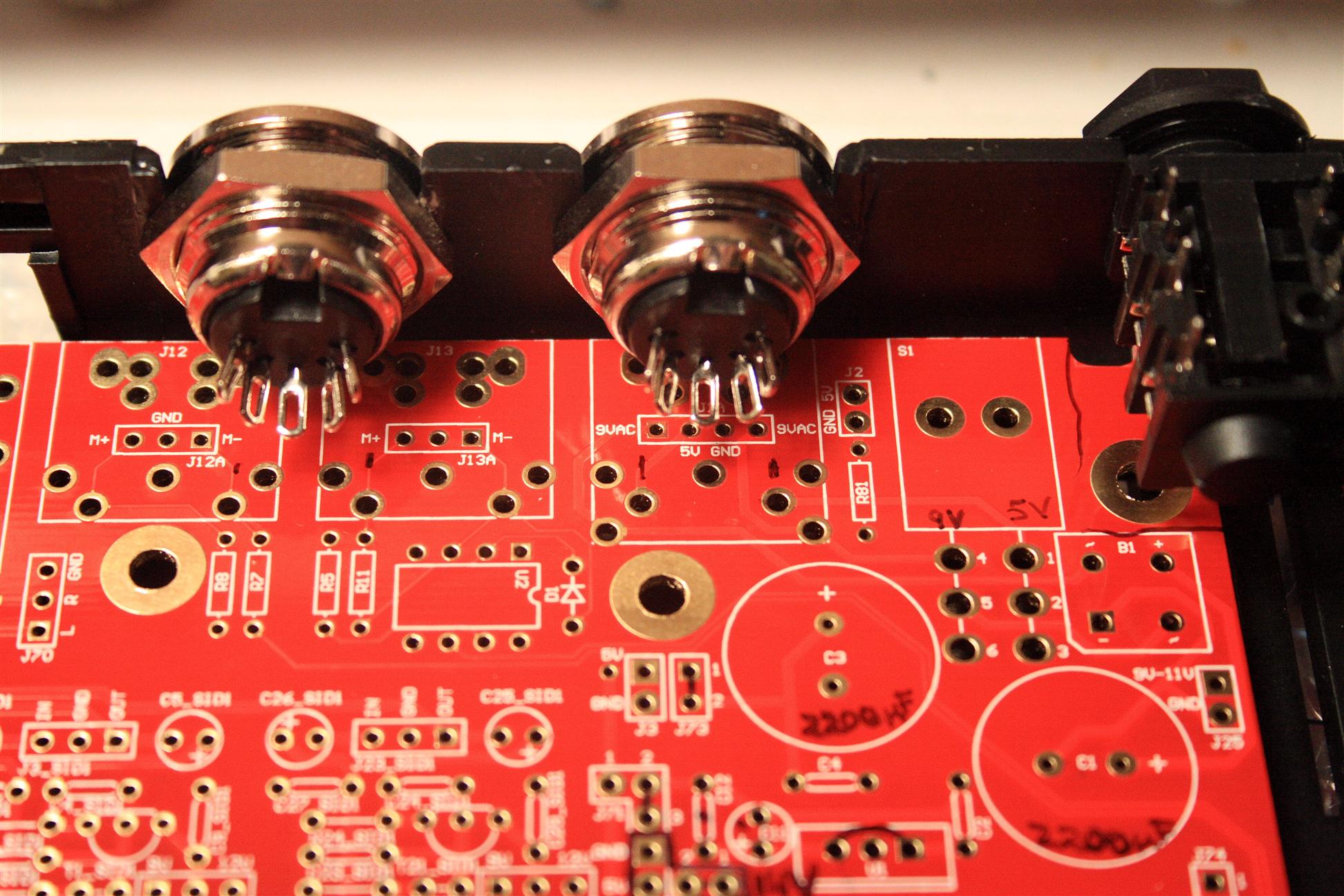
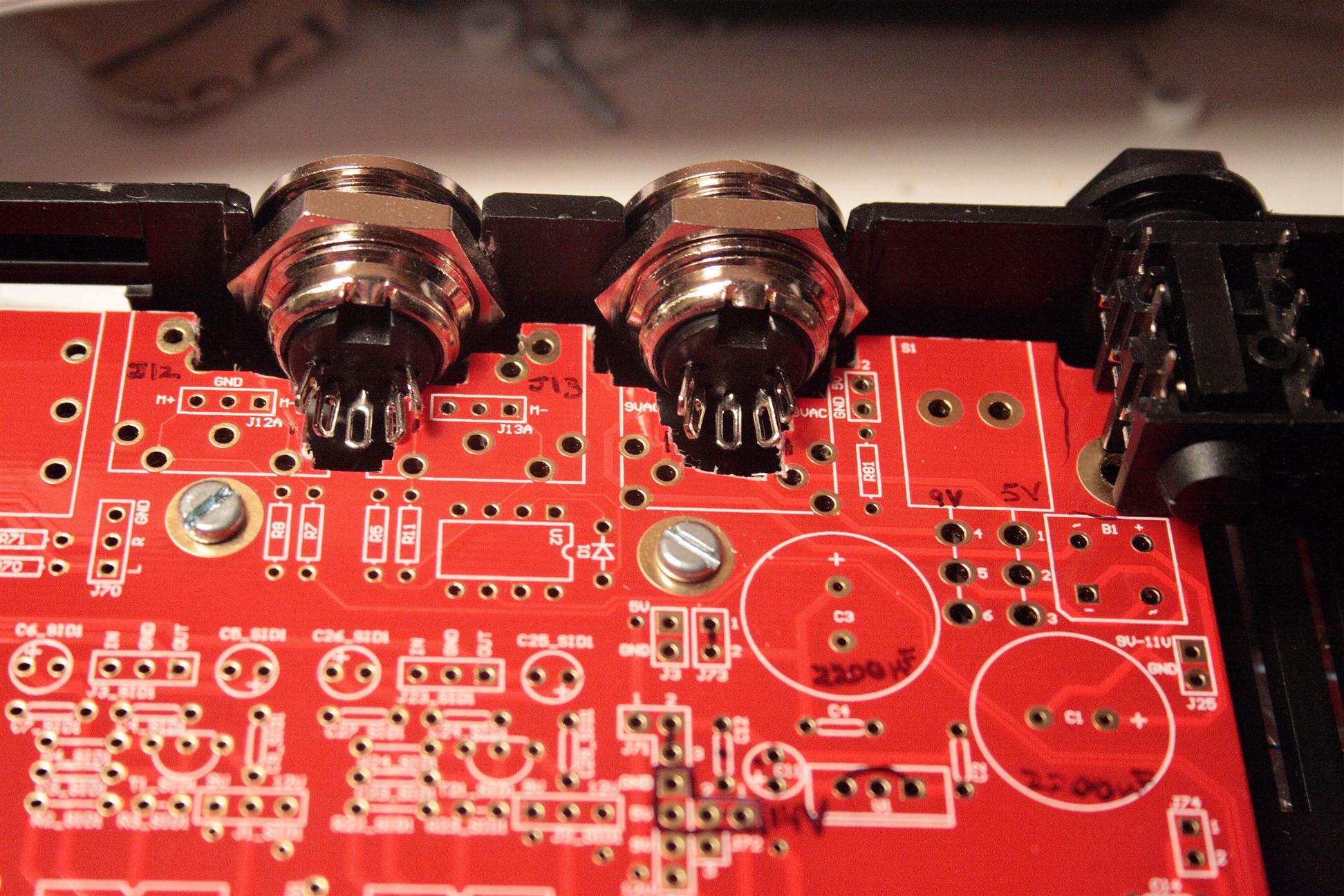
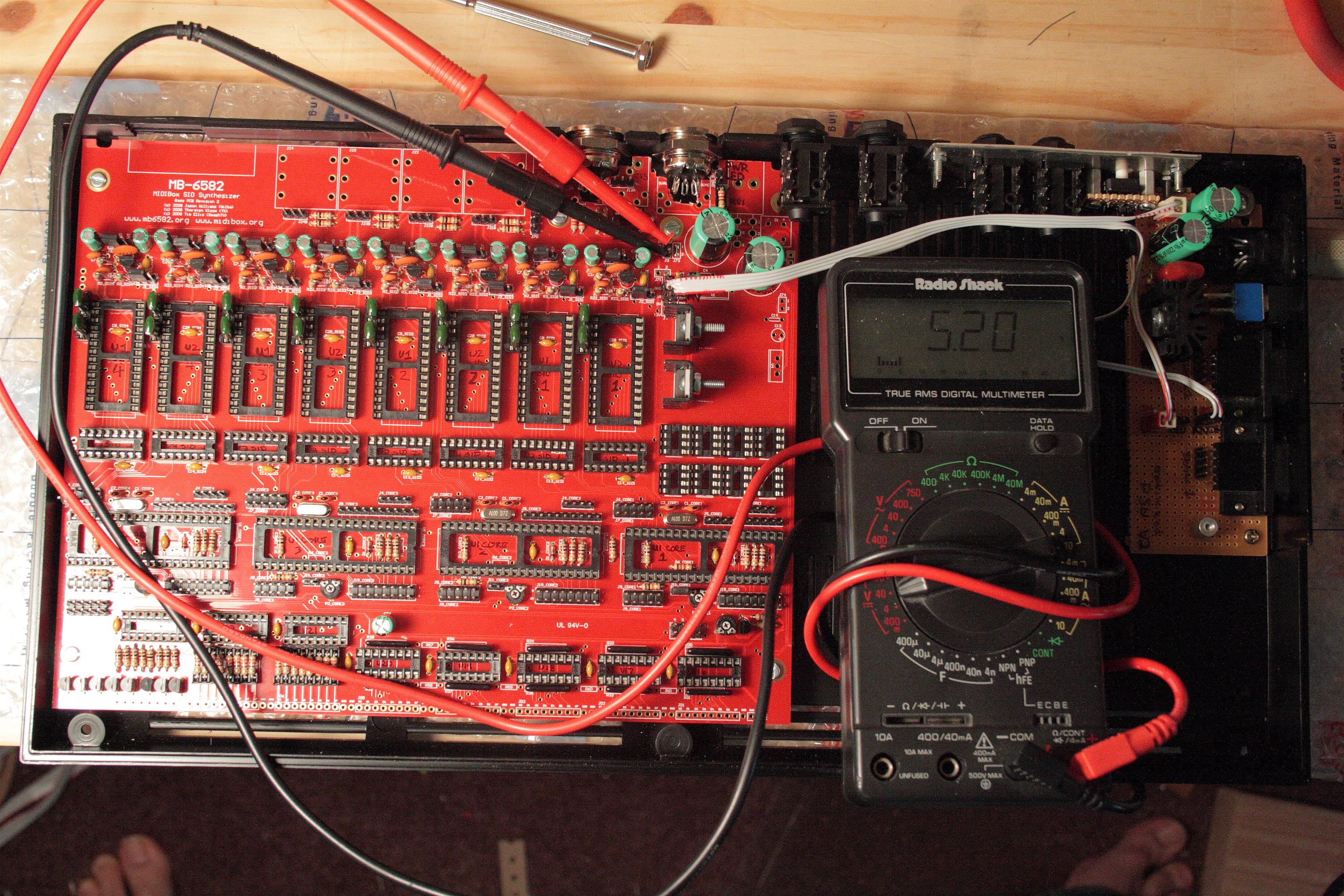
11am-12pm Soldered the PSU section using the "Option E" configuration I figured out yesterday:
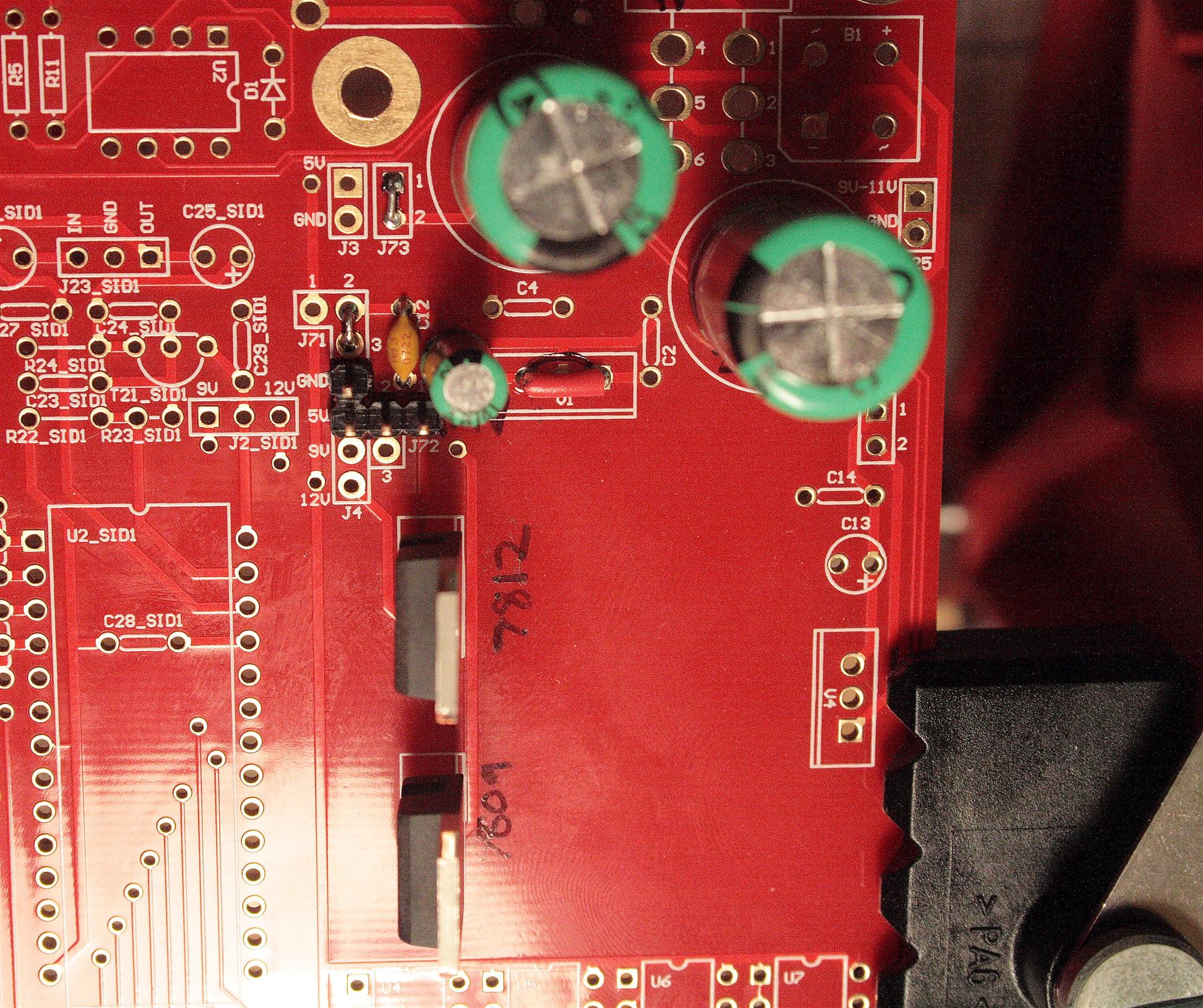
PSU section - The "L" shaped header gets 14V/5V/GND from the "optimized power supply" circuit
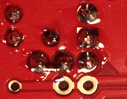
Don't forget to jumper J72 1&2... I did this on the back of the PCB
1:30pm-2:50pm Made a wire to connect the external PSU to the mb6582 board. I glued two 1x2 connectors together to make the "L" shaped connector.
Tested the power to the board, looks good, I see 5/9/12V at all the places described in the docs. For 5V I got 5.20V, but this is probably because the VREG isn't under a load yet...
Testing the PSU section, looks good... we'll test PSU again once everything else is stuffed.
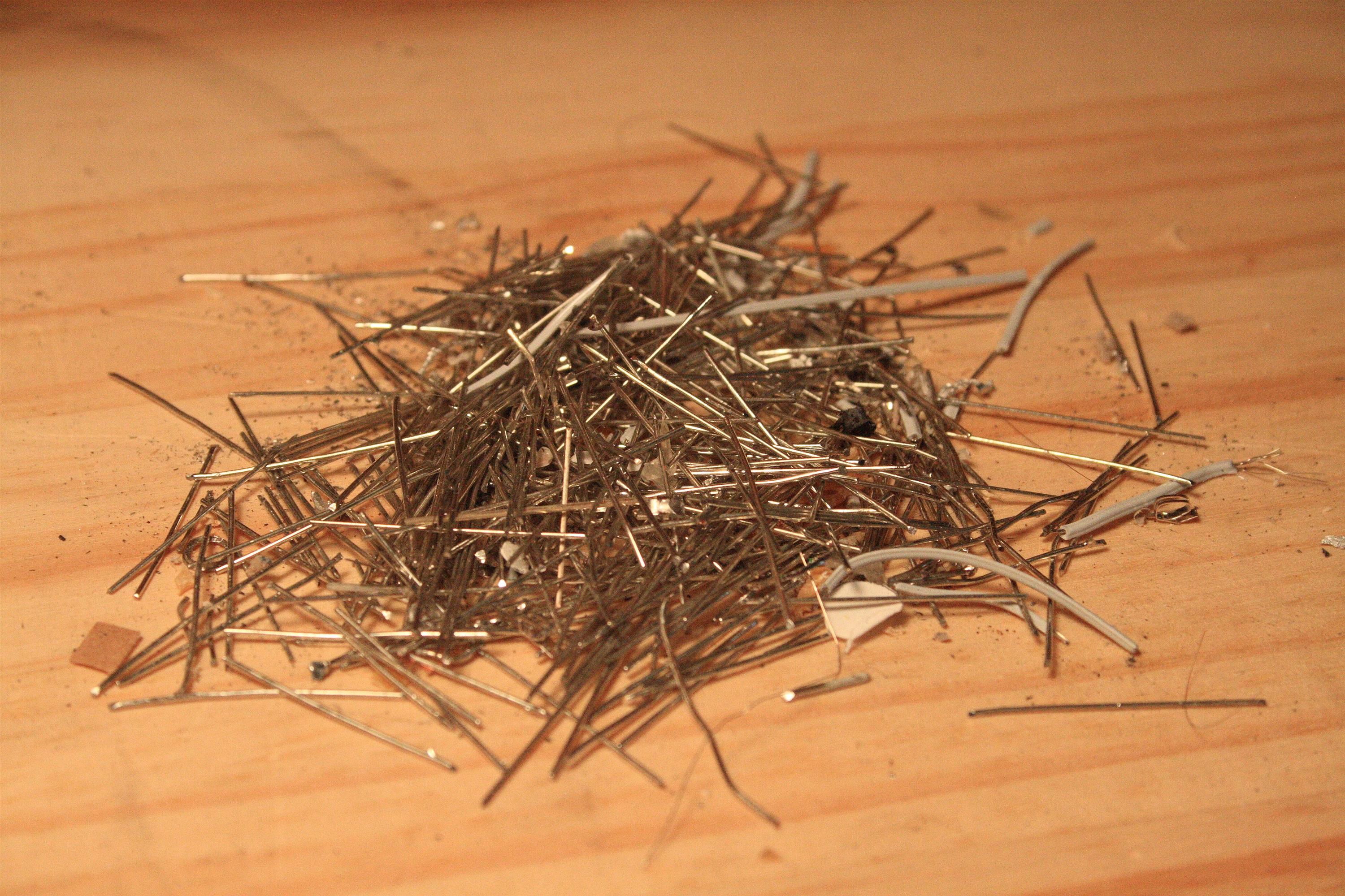
2:50pm-3:30pm Cut all headers for the mb6582 board... (I'll solder these in later...)
Headers
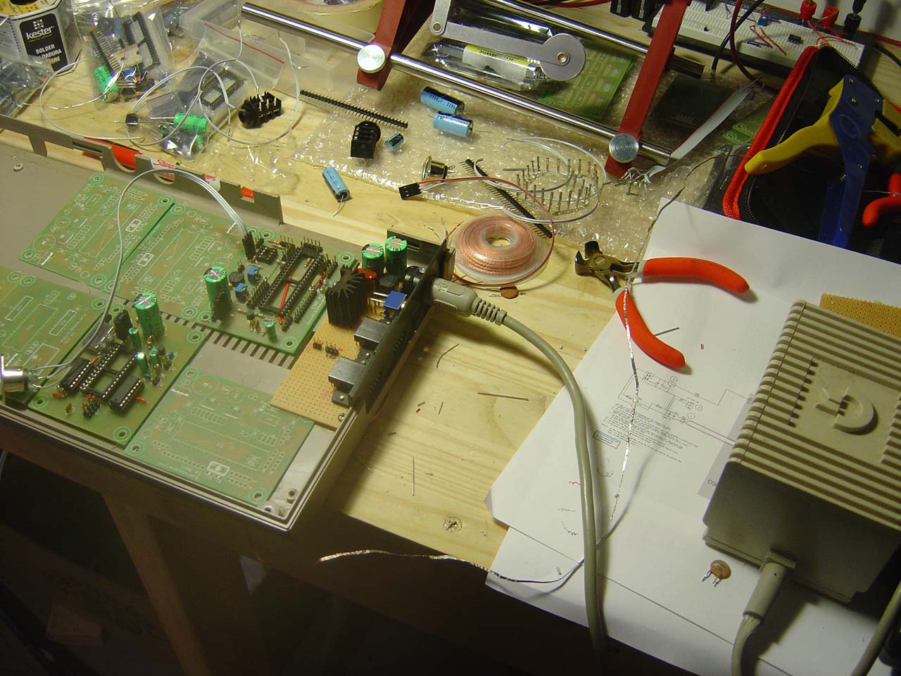
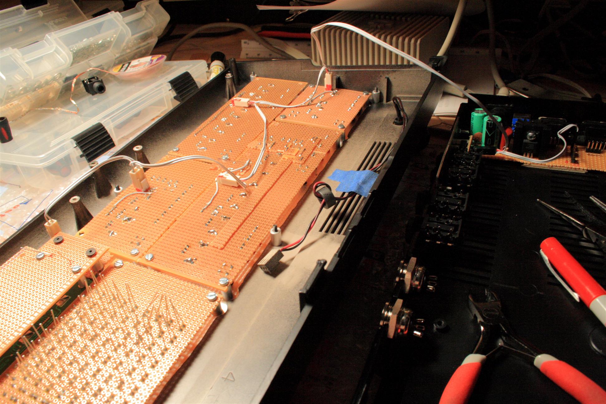
3:30pm-4:30pm Started on the Base PCB section... Time for some workbench shots before I run off to dinner at JapanTown...
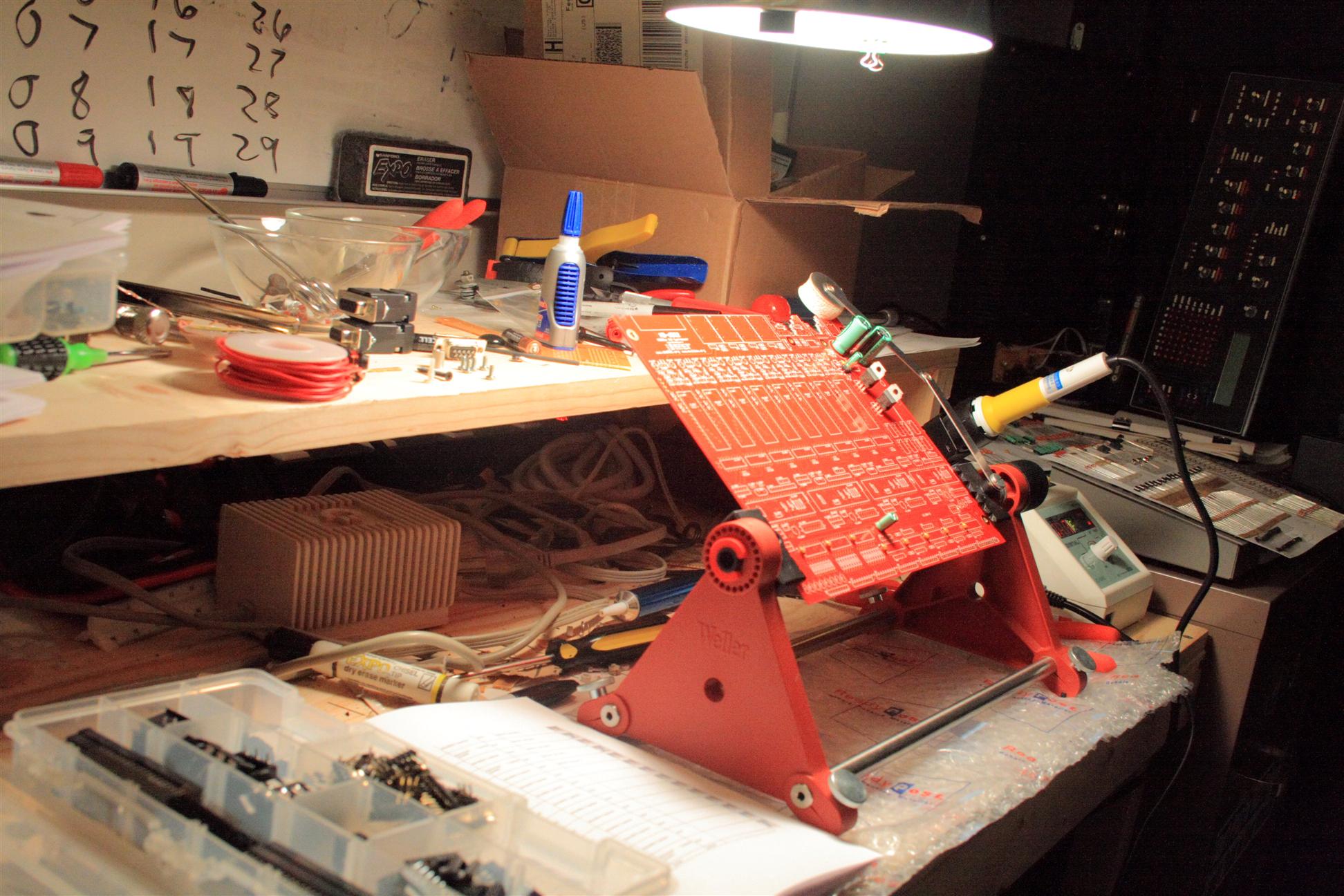
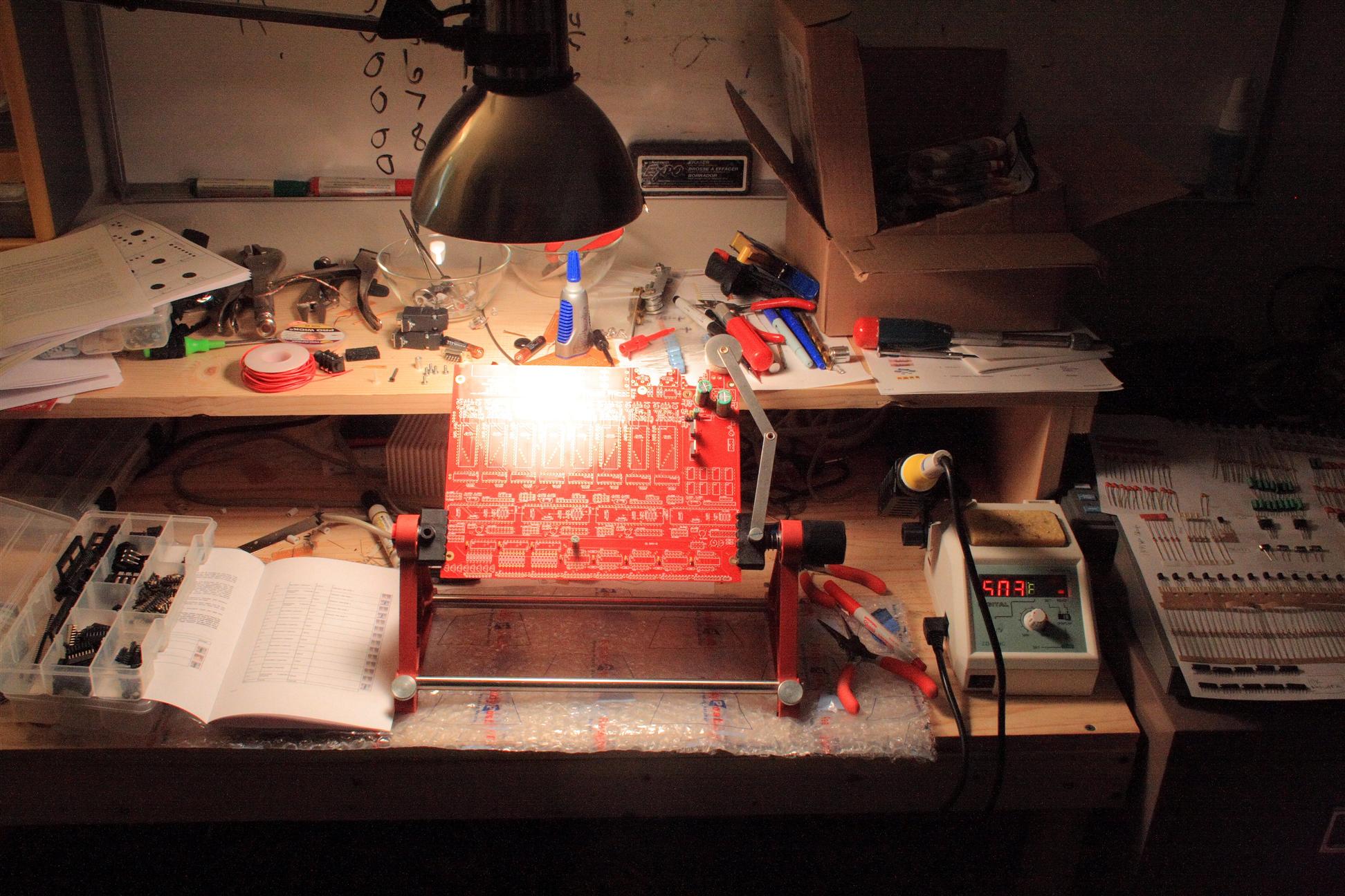
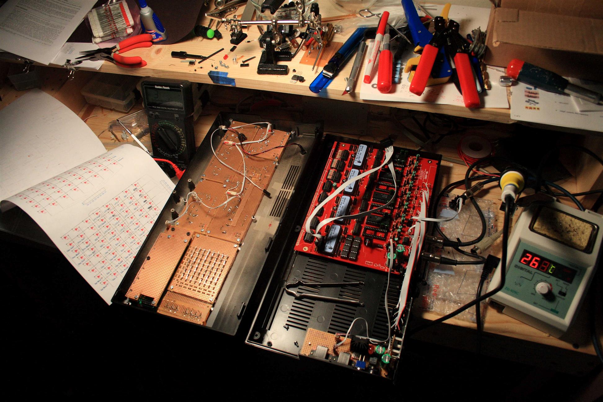
Workbench
.... queue anime and bad karoke music ....
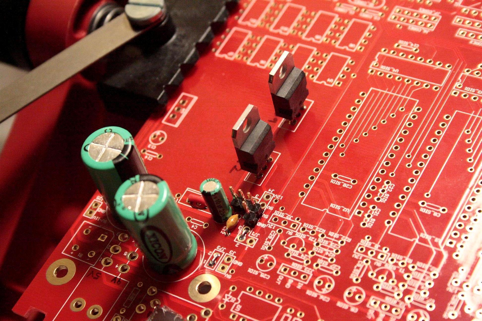
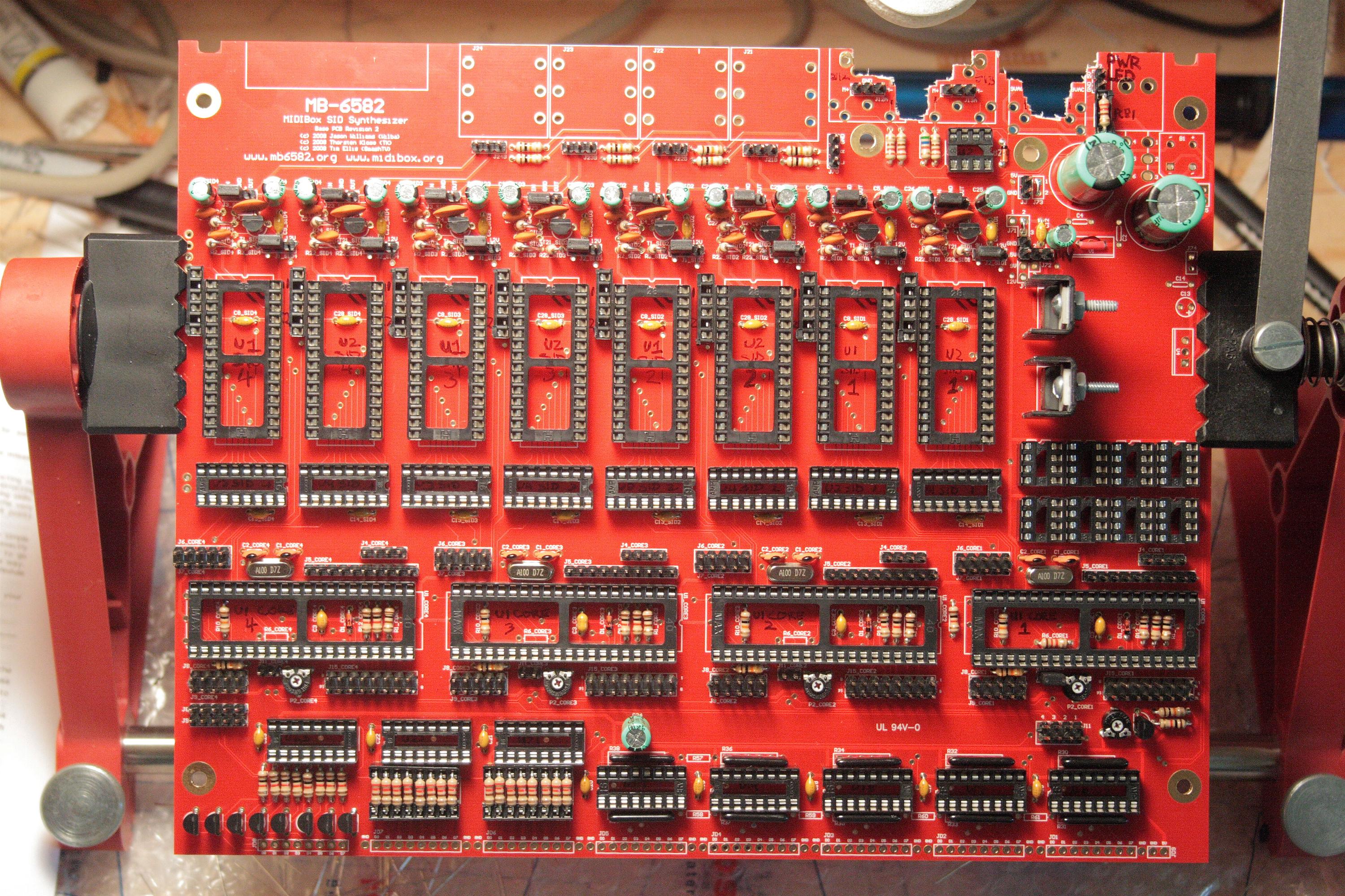
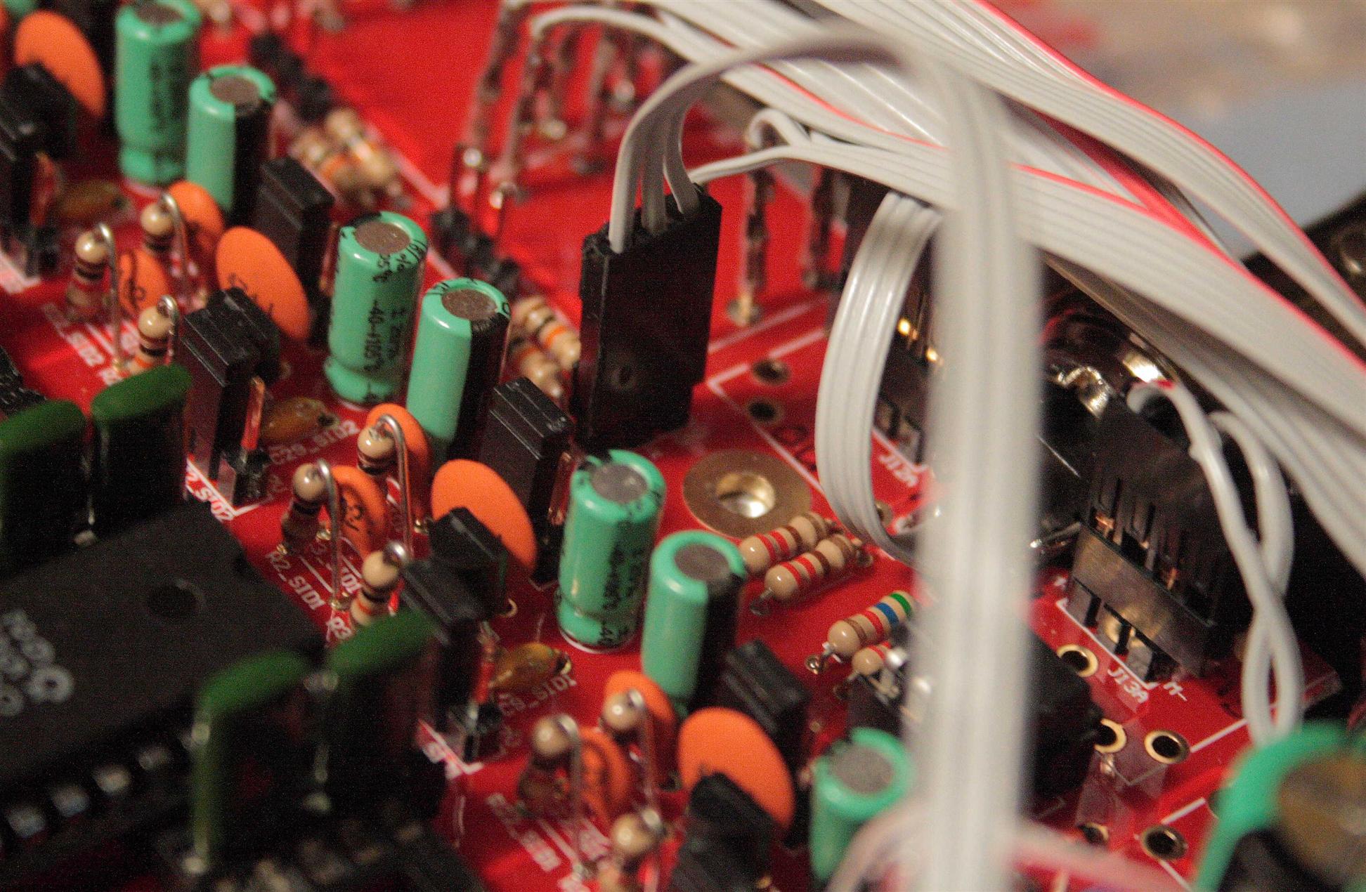
10:00pm-11:30pm Stuffed the components for the Base section... (had Udon and Sake at JapanTown, it was good!)
LED resistors. Socketed so I can adjust the LED brightness later
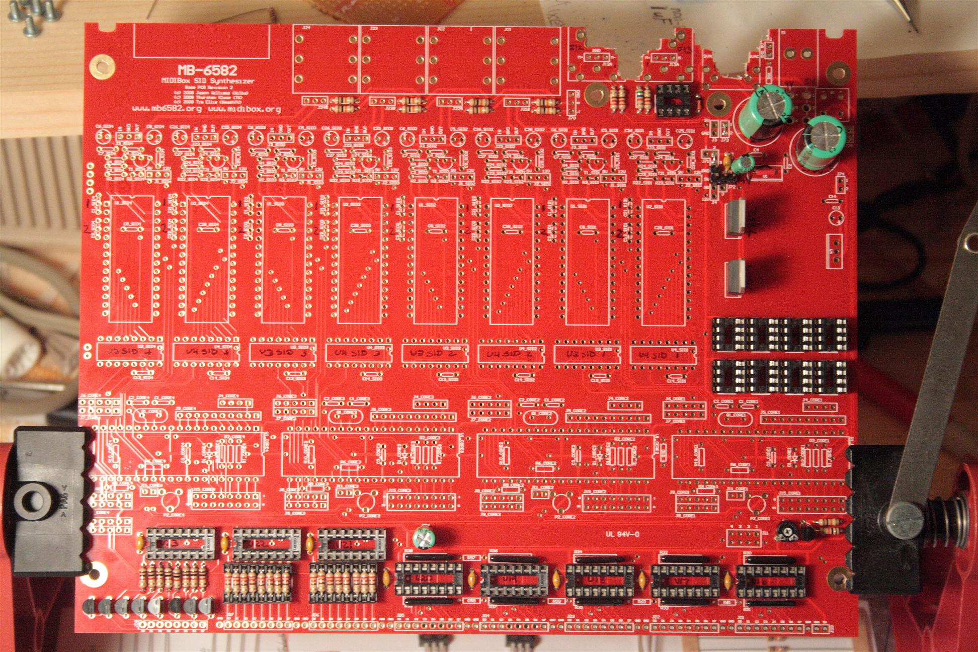
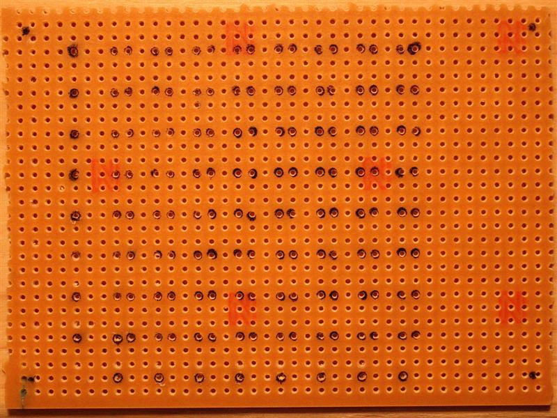
Base PCB section done
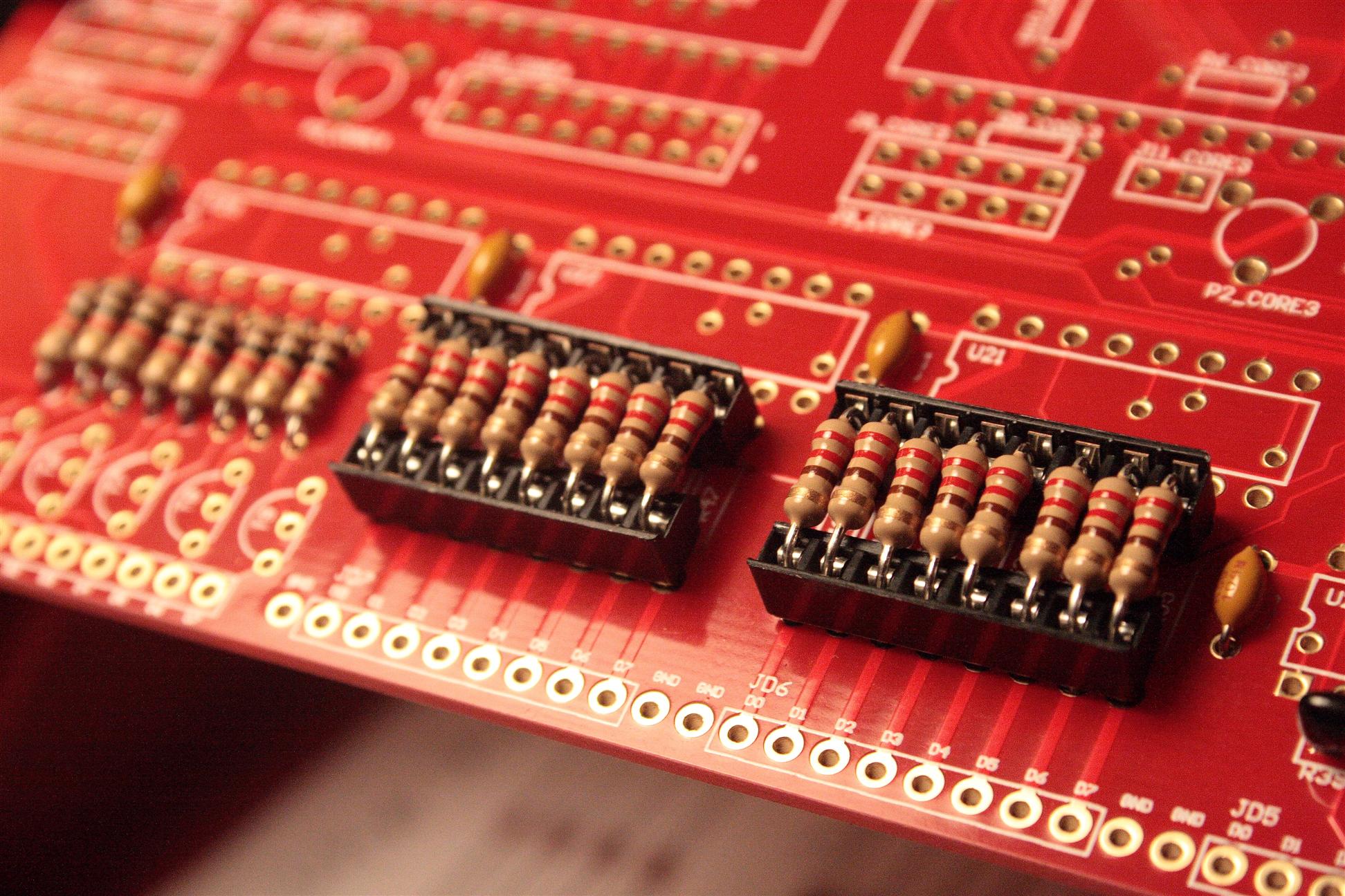
11:30pm-12:30pm Stuffed the components for the Core section...
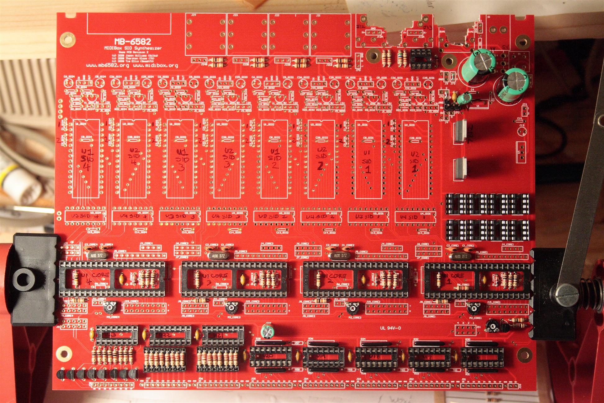
Core section done
You probably noticed my labels on the ICs. Basically the labels for the ICs get covered up by the sockets, so I wrote them where they could be read clearly using black marker. (I could just imagine coming back to install the chips and not knowing where to put them - yeah, I can always read the base PCB document to find the locations, but this small amount of work now makes the job easier later. and easier means less mistakes).
05.14.2008
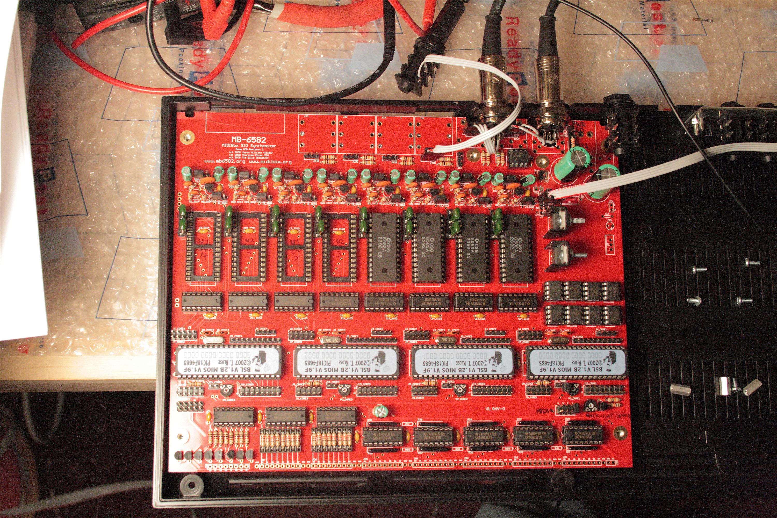
10am-4am I got pretty far today. Had some scares, some smoked parts, but in the end, I have 2 stereo voices controlled over midi. Basically, I smoked the LCD, no big deal, I needed an orange one anyway, so goodby green test LCD... and I have some weird voltage problem on the SIDs in the last 4 slots, they pull the entire system voltage down (i.e. 5V becomes 1V, not good)... It seems to be the slot, not the SID chip, that is the problem though, so I'm a little stumped at this point. My scare was when I put the cores in backwards. I was mesmerised by SmashTV's logo/stickers on them, and put them right side up, not paying attention to the chip orientation, only the SmashTV logo orientation. DOH. Remember kids, SmashTV logo goes _upside_down_ in the mb6582 PCB, not intuitive, I know, but try to pay attention like I didn't. :). Anyway, luckily I was ready with the power switch and caught it quickly (the 5V rail was at .6V so I shut down quick)... Anyway, they seem to work now, but that voltage problem still lingers, will need to focus on that tomorrow.
In the end I was able to hook up MIDI and then flash the PICs with the MIOS Studio with the latest mb6582 firmware (mios studio is java program for communicating with the midibox PICs), and then play some notes on MIDI channel 1 and channel 2 and hear the SIDs squarewaves in both ears. pretty cool!
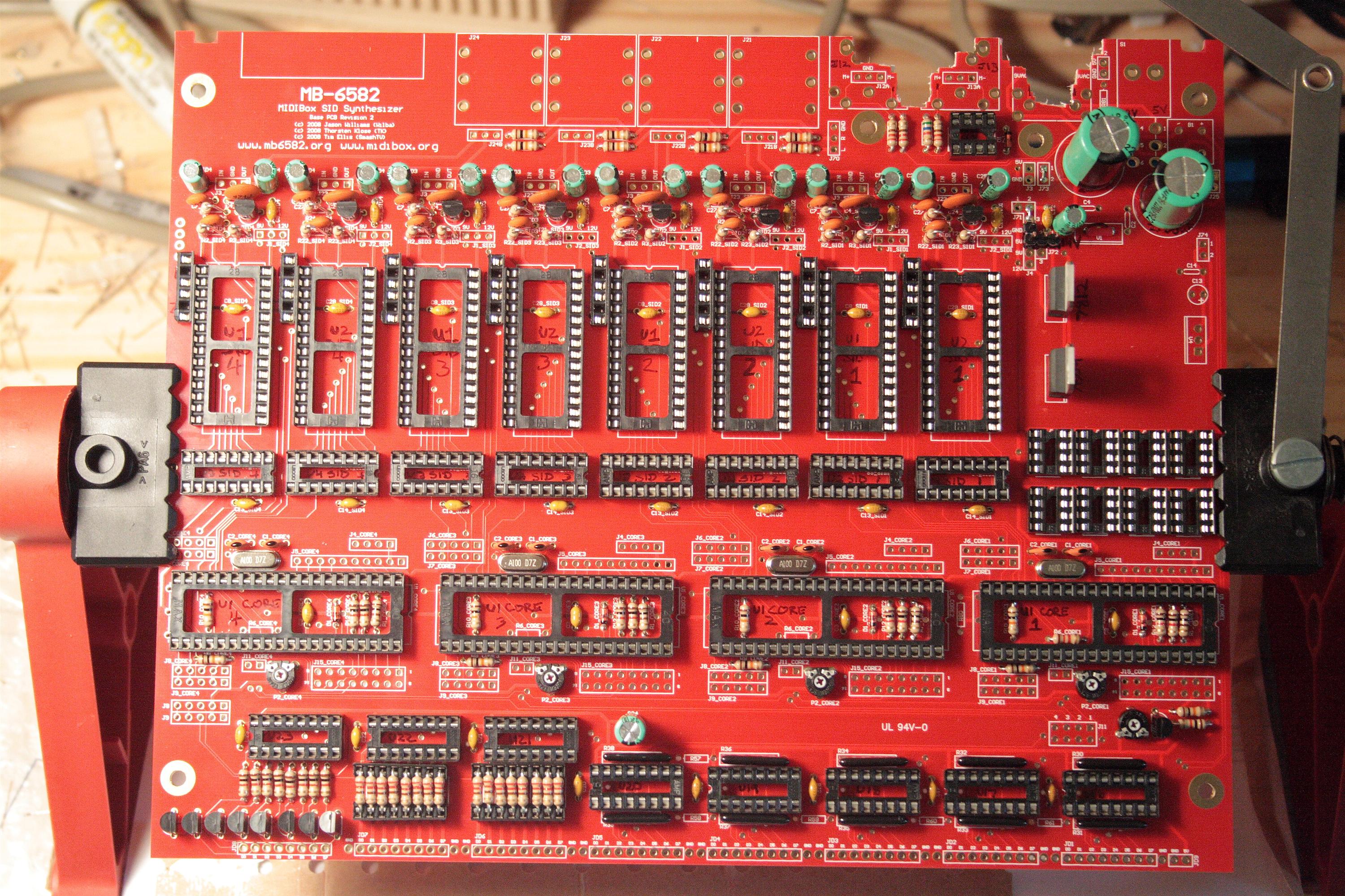
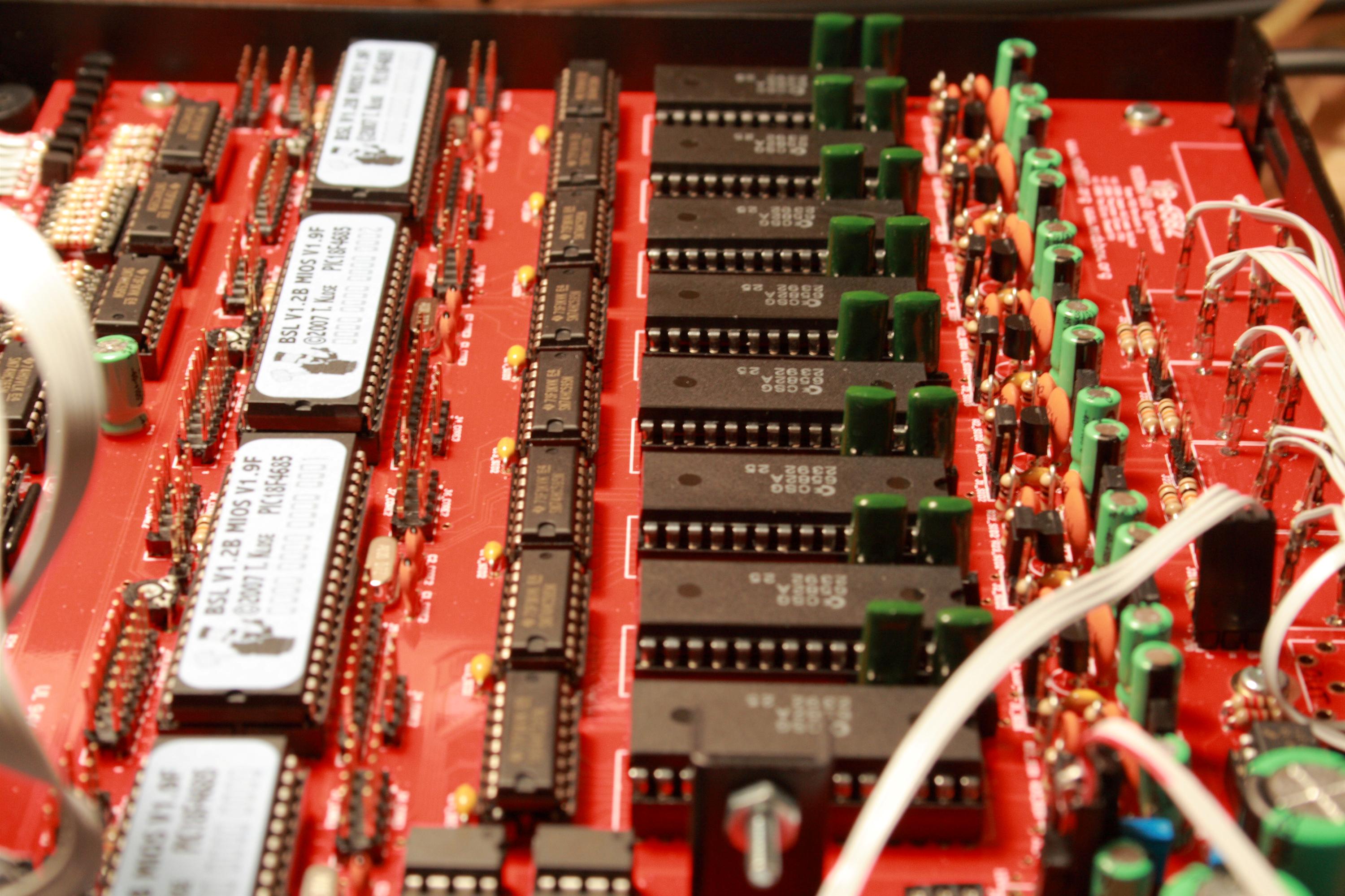
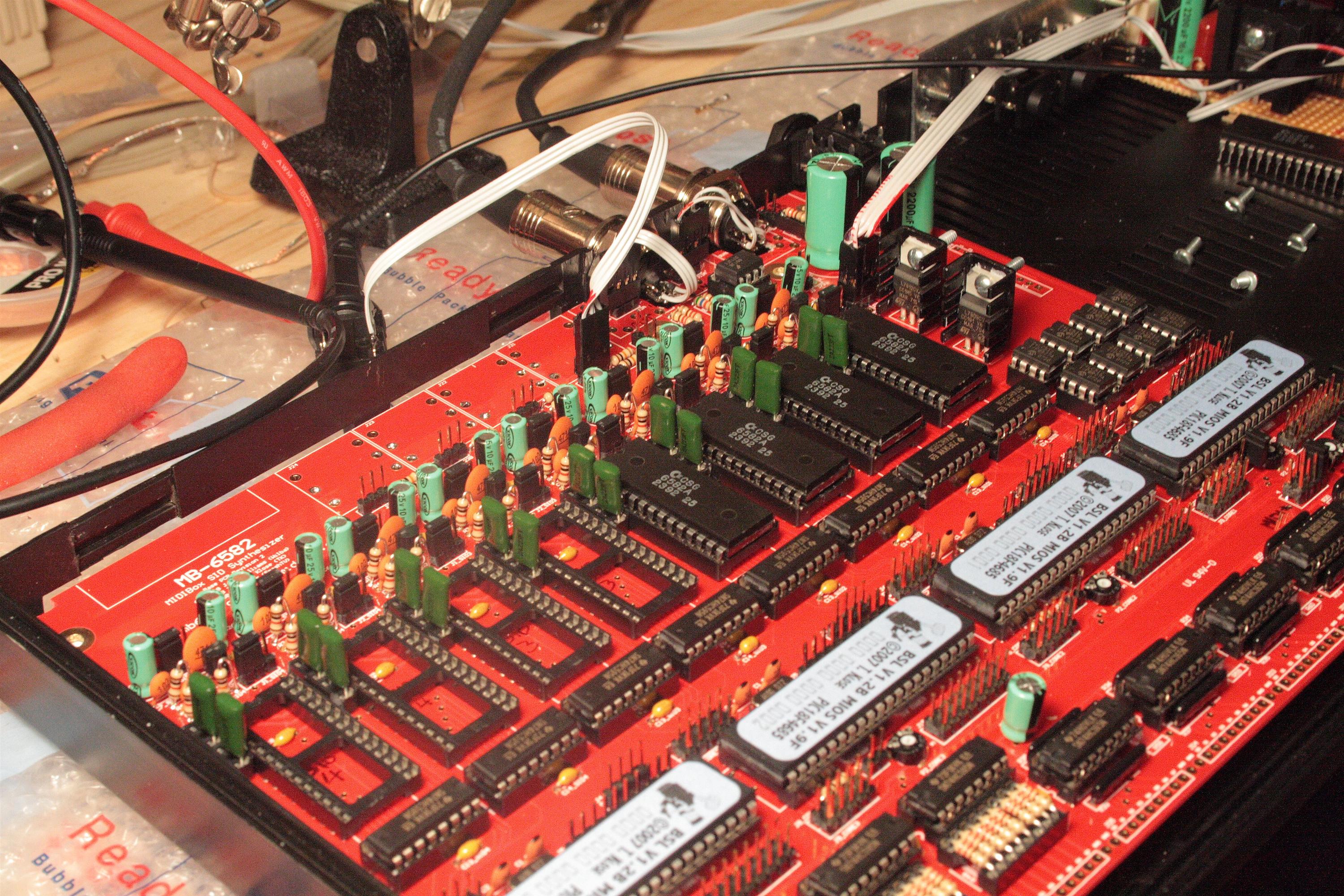
SID section done
Now, with headers...
The Aftermath
Ok, the board is mostly "done". Or at least it's now ready to put into the case and try to power on.
Testing for shorts and correct voltage
Ok, the moment of truth, lets put in all the chips. :) At this point, I probably should only have put in one core and one SID, but hey what could go wrong? Ok, lots. nothing worked at all when I turned the power on. which was a surprise, since all the power checks in the mb6582 docs checked out... ok, I measured .62V at the J3 (5V rail), that's not good. I quickly turned it off... I discovered the cores were in backwards, so I flipped them over (upside down, if you look at the labels), luckily I was watching the voltage as I powered on and caught it fast... Ok, now that's good, and I double checked all the other ICs. Ok. Do it again. Power on. ick, 1.6V ! WTF. ok... power off. no idea what's going on now. I go find my chip puller (I love these), and pull all the SID chips. I'm thinking at this point, yeah I should have tested more incrementally. Ok, power on with no SIDs, 4 COREs. Great, we have 5V/9V/12V as expected. ok. but ... I can't tell what it's doing since I have no I/O... hmmmm.... well, I plug in one SID chip just to see if we get ok voltage, and WE DO!. hmm... ok. Well as it turns out, I can add _up_to_ 4 SID chips. after that, the voltage drops and the device doesn't run... strange. Worried, I pull all the SIDs again. I try to hook up the LCD, and I hook it up wrong. NOTE to first time builders: 1-16 on the mb6582 does not correspond to 1-16 on the LCD. Seriously, go look up the LCD wiring diagram on the midibox website, and pay close attention. I asked Wilba to change the silkscreen from 1-16 to instead match the .PDF to prevent other people from making this same mistake.
Ok, so I burnt out my LCD, it got hot and smoky and stinky. But that's OK!, I needed an orange LCD anyway, for my control panel's color scheme. great, so here's my motivation to drop $40 on that. So I go order it, then come back. still confused about the power problem, and now with no way to test. hmmm, but that's not true. I have MIDI jacks! woo. ok, obvious, sure. So I hook up the jacks, and go read the SID manual where it described using MIOS Studio (a java based program for communicating with your COREs over midi) and how to upload the "MB-SID application" to the COREs. Ahhh. So it dawns on me that the COREs I got from SmashTV are not preprogrammed with MB-SID firmware, rather they're only preprogrammed with MIOS, which is kind of a bootstrapping kernel for recieving these applications onto the firmware... ok cool, so I flash each of the 4 COREs, changing jumper J11 each time to switch which CORE has midi input, and ok, good, done. At that point I hear lots of beeps and such. JOY!. Ok, the SIDs (or one of them at least) work. I can hear it. ok. I try some notes on the keyboard, and yep, still works. cool. So things are looking really good. If only there wasn't this power problem.... I'll look into that tomorrow.
hmm, only 4 SIDs work, strange... :(
05.15.2008
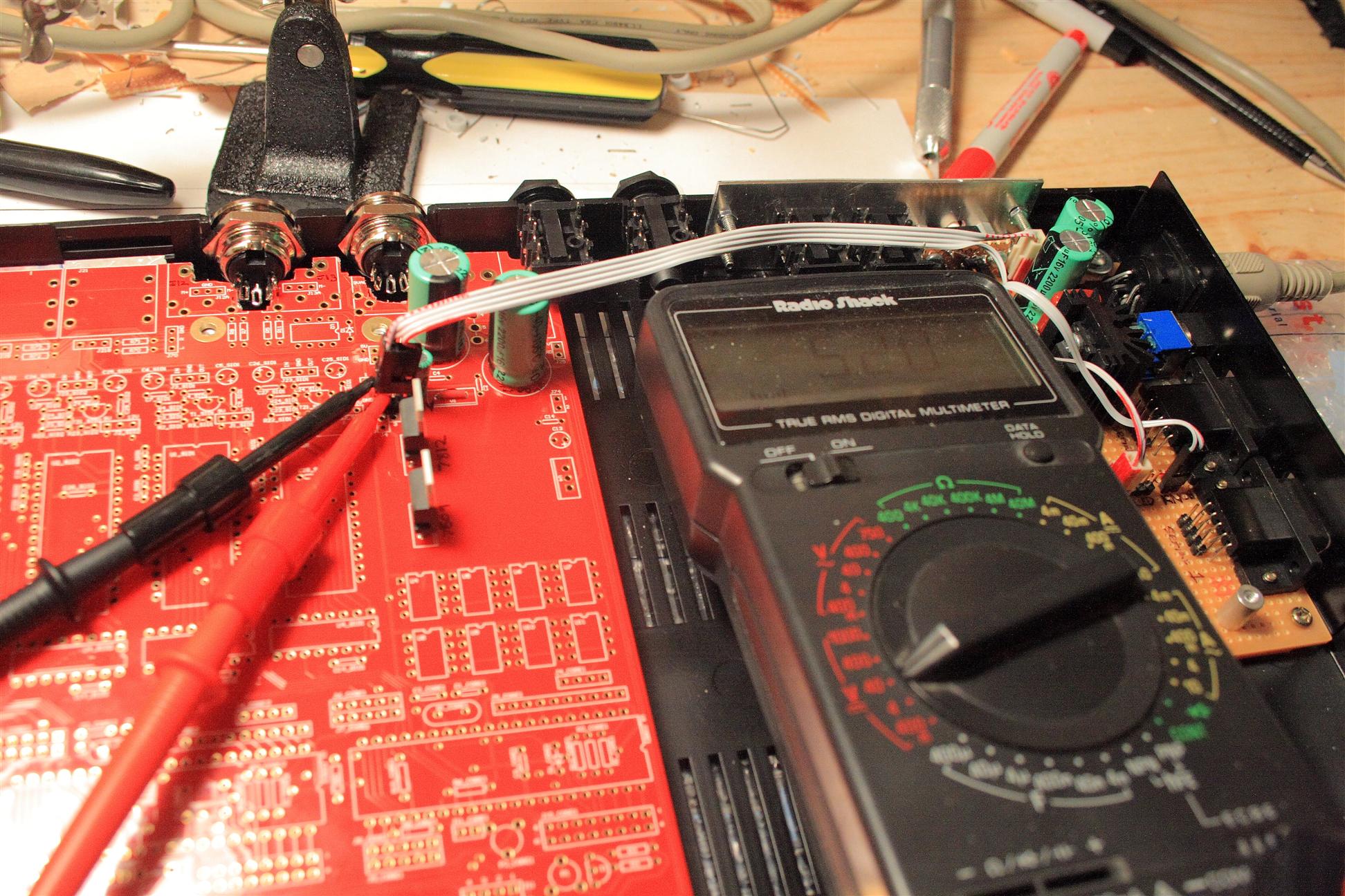
8am-6pm mostly futzing around today. Thoroughly tested each SID chip individually (for my own confidence), all checked out ok, making sounds, good power supply reading, etc.
also taking lots of measurements trying to figure out the power problem. It looks like it's related to the PSU not able to supply enough current. Strange. Previously I had thought it was related to which slot a SID was plugged into, but NOT SO!... If I use _more_then_4_ SID chips, in any slot, then the voltage drops to around 1V, not enough to drive the device (nothing turns on)... Looks like the current (Amps) maxes out around .565A on the 5V line with 4 SID chips... The 5V line comes straight from the C64 PSU, so maybe something is wrong with the PSU, it is supposed to be able to supply 1.5A and we're only seeing 1/3rd of that...
I took current readings on the 5V supply line (in between the C64 PSU and the mb6582 board.)
0 SIDs 5V   .17A
1 SID  5V   .27A
2 SIDs 5V   .37A
3 SIDs 5V   .5A
4 SIDs 5V   .565A   (peak number of chips, after this,
5 SIDs 1.6V .386A          nothing functions, current drops)
6 SIDs      .338A
7 SIDs      .309A
8 SIDs      .290A
Strange huh? The little C64 brick PSU can't keep up, or something... It's rated for 1.5A on the 5V line, the 5V line goes straight to the mb6582 board (i.e. I didn't insert any circuits to screw that up), and it seems to only be able to put out .5A, 1/3rd of the rated current for the 5V line... very sad indeed.
In any case, despite the problem, I have myself a pretty cool little 4-SID monosynth now. No control surface yet, but the midi and audio jacks work. I uploaded the sysex file for the factory presets, the utility I used didn't work well, and I only got 64 presets - every other one on one bankstick only. The other banks were filled with default square wave, no idea if that's correct, but i'm guessing not... The utility I used was syx2mid, some ancient dos program so I could "play" a midi file to transmit sysex from the midi stream. Anyone know a good sysex tool for windows?...
UPDATE: Steve suggests MIDI-OX, it does sysex stuff on windows. Thanks!
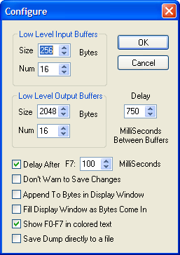
UPDATE: Here's some settings Wilba recommends to make MIDI-OX send your .syx file without errors
Here's me playing around with some sounds for the first time.
![]() test1.mp3
test1.mp3
![]() test2.mp3
test2.mp3
![]() test3.mp3
test3.mp3
![]() test4.mp3
test4.mp3
![]() test5.mp3
test5.mp3
![]() test6.mp3
test6.mp3
1xSID sound check (only 1 voice)...
![]() testsong.mp3
testsong.mp3
4xSID test song... (4 SID voices, + drum samples)
I also took a little time today to hook up the audio jacks properly. I simply wired them over to where they would normally PCB-mount, I did this because the audio jacks are switched and the mb6582 board is wired such that each SID output jack, when unplugged, automatically inserts into the mix out jack (which I still need to wire up and mount onto the case)...

4-voice mono SIDs, pretty cool
I also noticed that the SIDs get pretty hot to the touch when you leave the mb6582 on. Not burning hot. But if you hold your finger there a while, you get used to it so that you think they're only "warm". So I don't think it's a problem. but yeah. a little hot. I worry about that much heat all sitting inside my case... I really don't want to use a fan... Maybe I can find some DRAM heat sinks to use on them. :) I wonder if the SIDs could draw less current and still be happy, and less hot... might be worth trying... but I'd have to cut a trace on the mb6582 PCB.
05.16.2008
9am- Today I tried my bench PSU (GND/5V/12V/-12V) on the MidiboxSID, It was easy to plug in to the mb6582 base PCB. (I just plugged into the existing GND/5V/14V socket since we don't really need 14V, 12 works just fine). All 8 SIDs run !!! ok, so my sagging voltage problem was definitely a PSU problem... going to think about how to resolve this.... UPDATE: I basically need to try another PSU... need to buy one or find someone now...
--- with bench power supply and all 8 SIDs ---
5V line - .96A
14V line - .156A
UPDATE 05.31.2008: I got a new PSU off eBay and tried it tonight with 8 SID chips, and it works. So, now I know the power problem was all in the "brick" PSU I had... The new PSU is black, so it matches better anyways... go check out some stereo sounds and pictures of the 8 SIDs stuffed...
05.17.2008
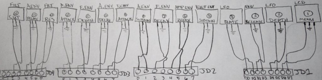
3pm-5:30pm well, I'm waiting for a shipment of headers and connectors as well as a new LCD, so today I took a little time to plan out the control surface wiring. I mapped it all out on the mbsid-V2 control surface I'm using. check it out, it might save you some time if you're building the default panel with the mb6582 PCB:
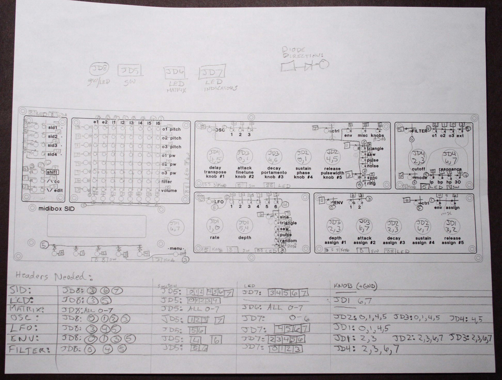
wiring diagram to connect mb6582 PCB to the V2 control surface
shows wiring, and gives an idea of how many header pins are needed per control surface module
NOTE: the JDx names refer to these diagrams: mb-6582_cs_dout_wiring.pdf, mb-6582_cs_din_wiring.pdf, mb-6582_base_pcb_b_w.pdf
05.19.2008
3pm I took a break yesterday to go see Indy4 (screening), and work on some x0xb0x mods (i added 18 holes, it's like golf!).
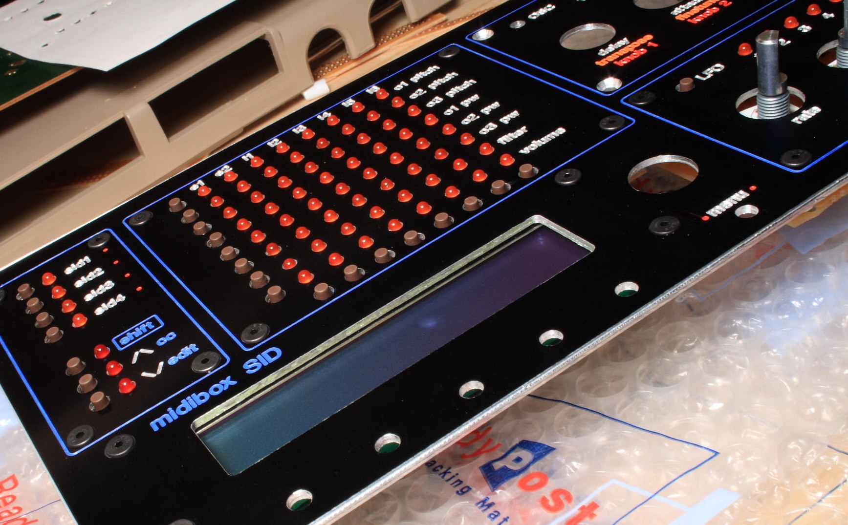
Today... The new orange LCD arrived in the mail, and after rechecking my wiring for mistakes, and I took a chance and hooked it up. It worked! Great. Ok, so here's a picture and a connection diagram for you.
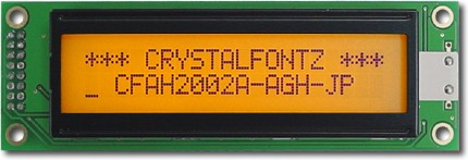
The new Orange LCD - CrystalFontz CFAH2002A-AGH-JT
LCD eye candy
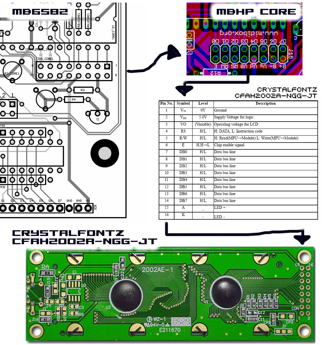
LCD connection diagram
05.20.2008
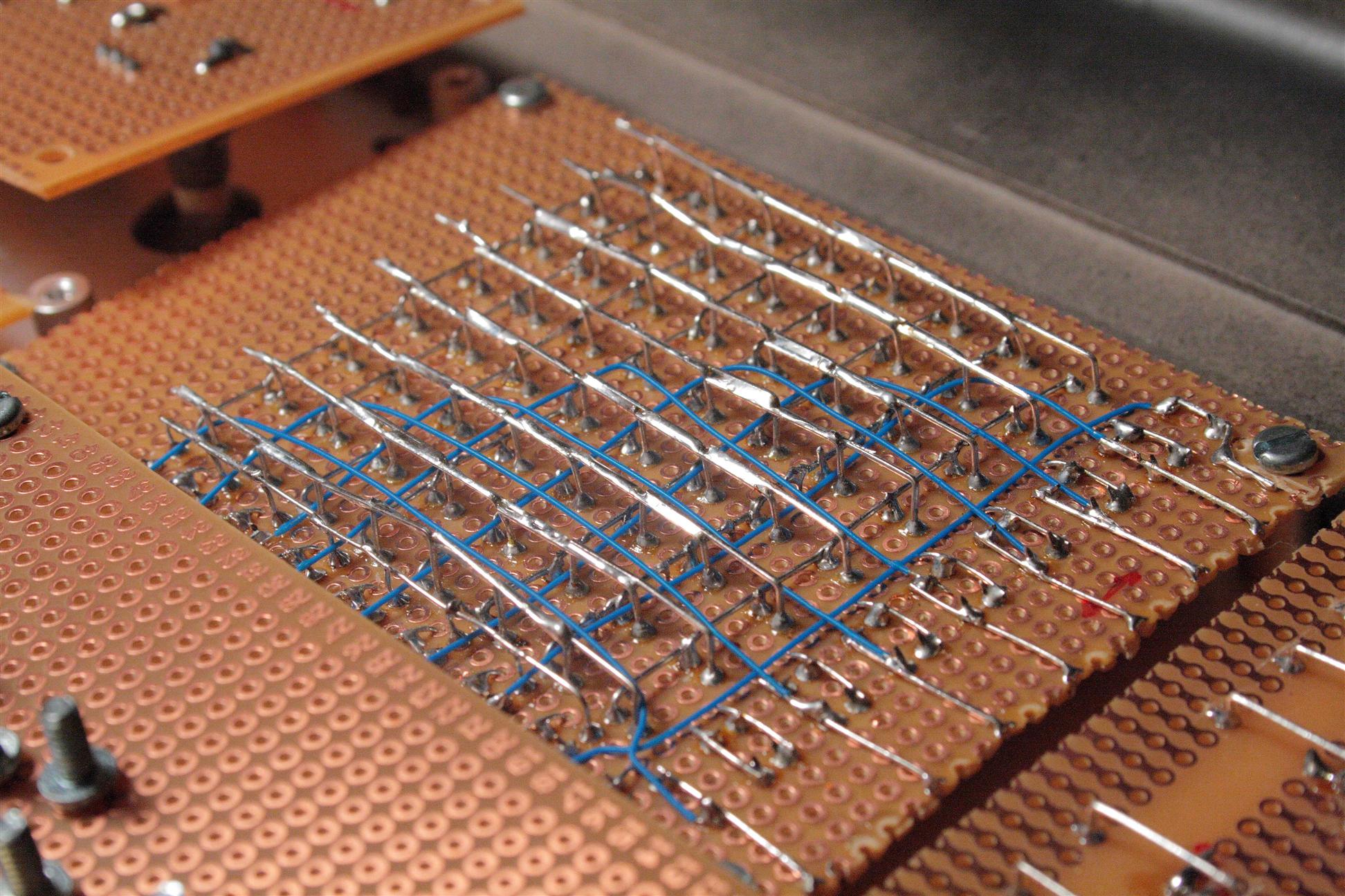
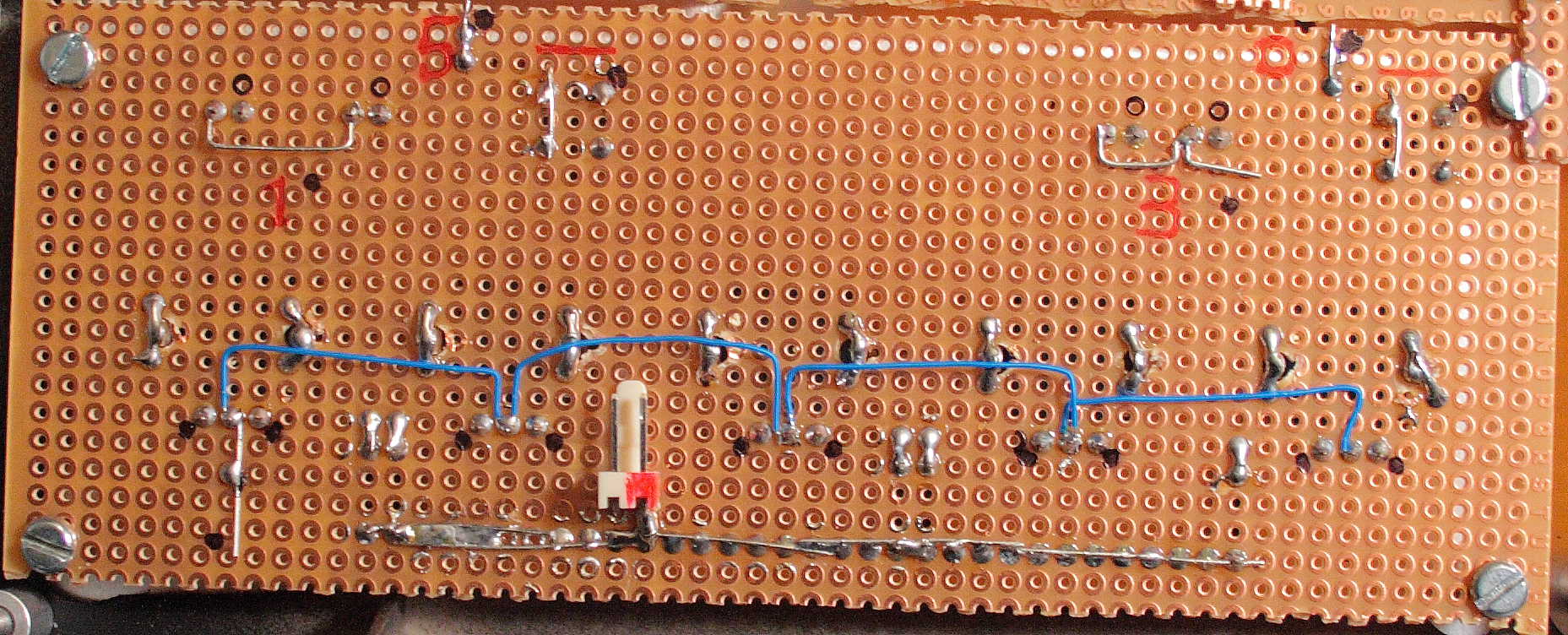
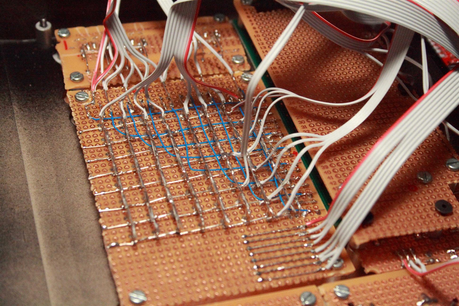
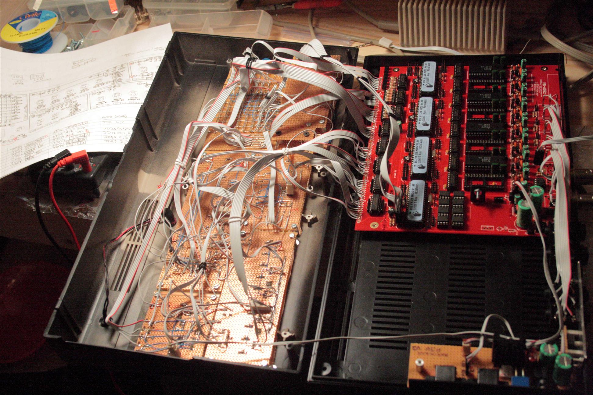
On the 17th, I made a wiring diagram, so today, I started wiring the modules to match. Getting the modules ready to wire to the base pcb.
the new workspace, side by side - working on the matrix wiring
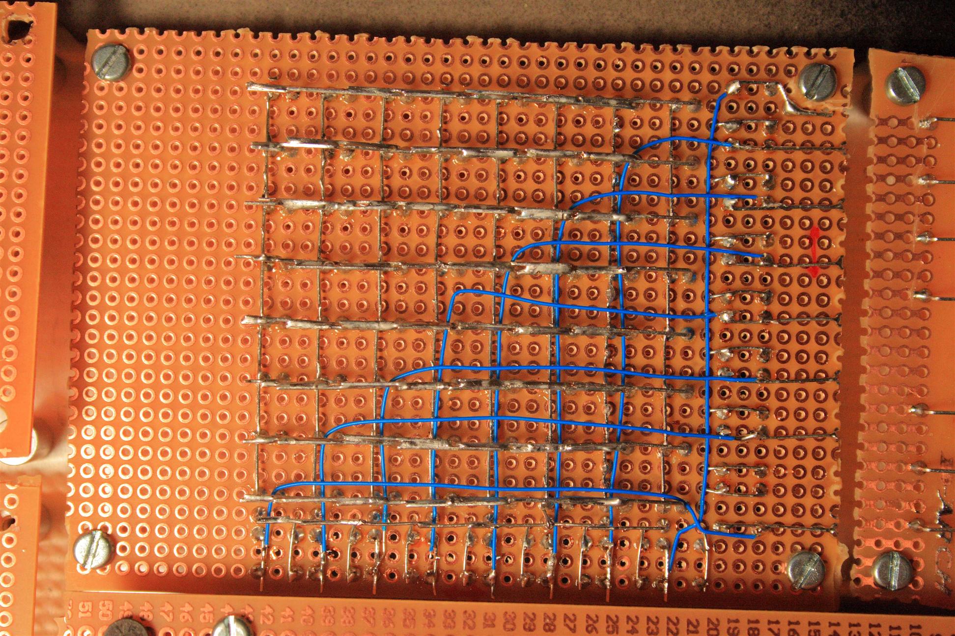
Adding wires per the wiring diagram
Alternate views...
05.21.2008
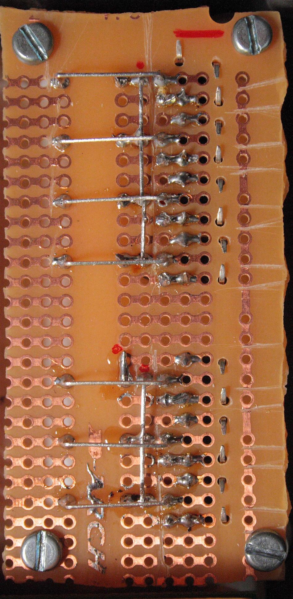
1pm - 6pm Today I finished up the module wiring I started yesterday...
![]()
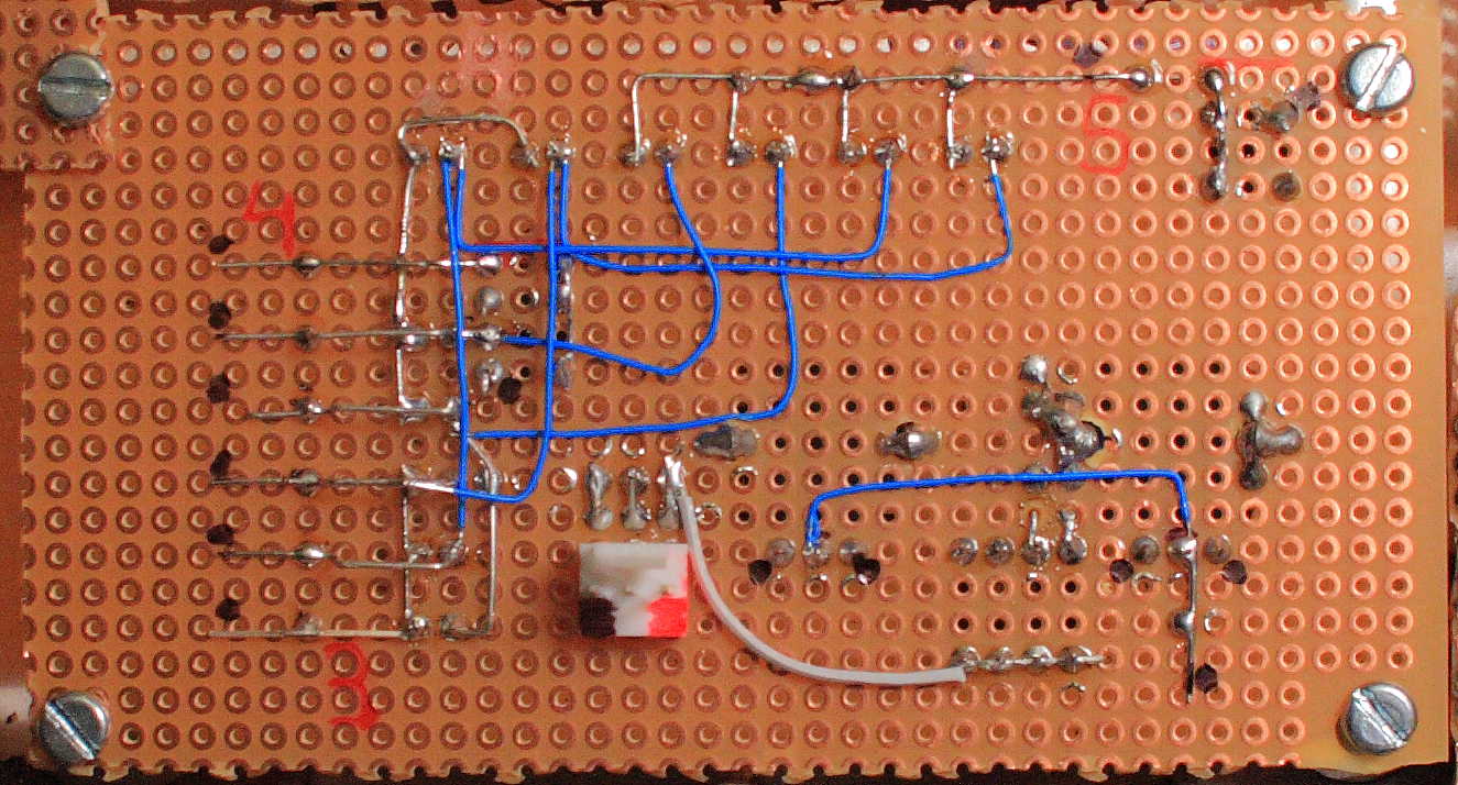
Adding wires per the wiring diagram
control surface done for now... Ready to wire direct to the base mb6582 pcb
After I finished each module, I used a diode tester on each signal path (switch or LED), to be sure we had the proper paths, checking against this wiring diagram.
05.22.2008
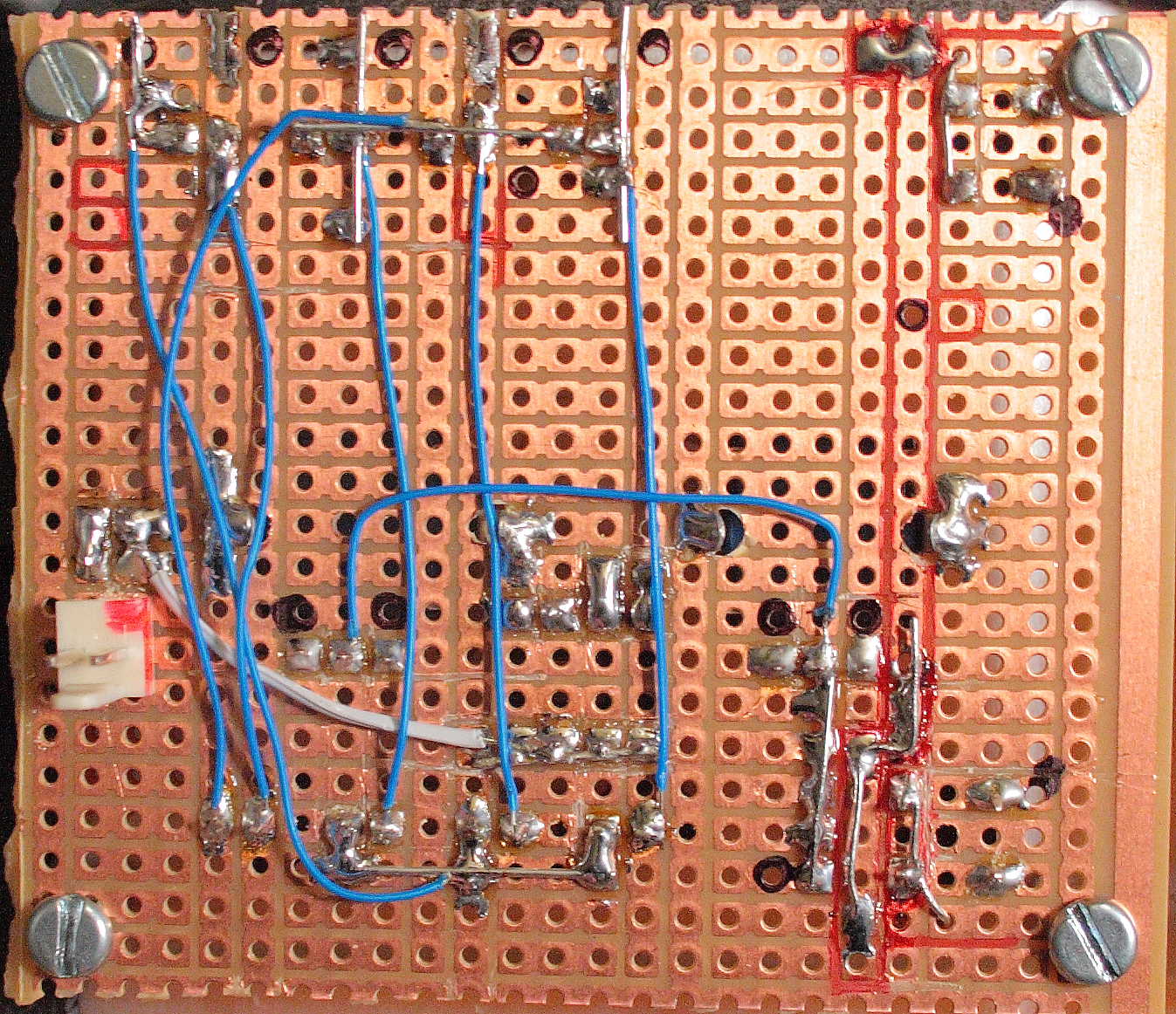
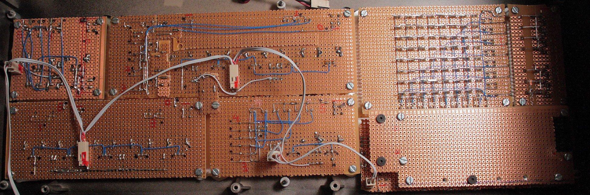
4-6pm hooked up a very basic control surface, mod matrix and menu. both modules seem to work except the "menu" button, but it's hooked up according to the mb6582 DIN wiring diagram, so maybe i'm not using it right... no idea. will figure it out later.
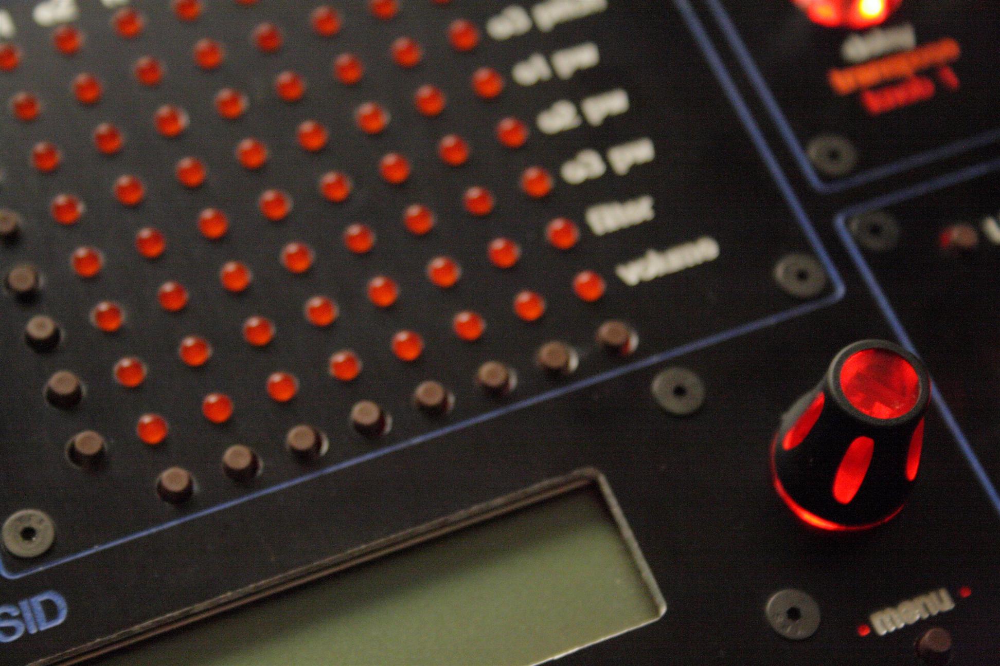
So, a note about my wiring strategy I'm going to make the mod matrix module sort of a "junction box" for all the other modules, at least where lights/buttons are concerned. The mod matrix is special because it takes all of JD5, JD6 and JD8 and has a lot of surface area for splicing on connections. So, this way, I get minimal ribbon cabling going over to the mb6582 base PCB, and keep the mess up on the control surface modules... I even added a tiny bus for the JD7 connections.
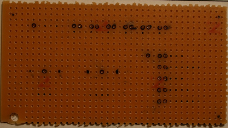
Hooked up Mod matrix and Menu sections.
Mod matrix is a "junction box" for 4 "busses", JD8, JD5, JD6, JD7, which we'll use to connect other modules.
UPDATE: There was a bug in the connection diagram, the menu button needed to be on JD5 pin3 (not 4).
05.24.2008
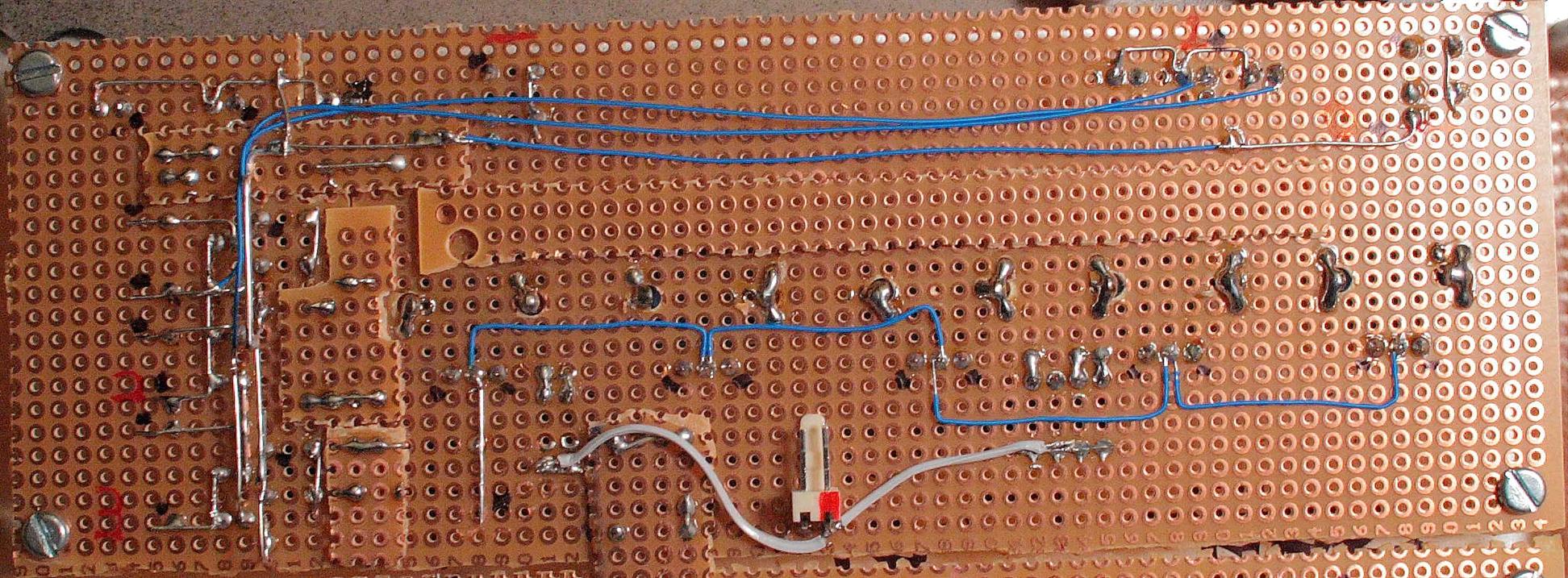
1-6pm hooked up all indicators and buttons. I'm so glad I created the wiring diagram. I'm doing the control surface wiring completely off this diagram, and it's really made the work go smooth.
Not working: shift PgUp/CC, PgDwn/Edit, I'll have to hack the firmware for these, since wilba's mb6582 has these 2 buttons separated into 4.

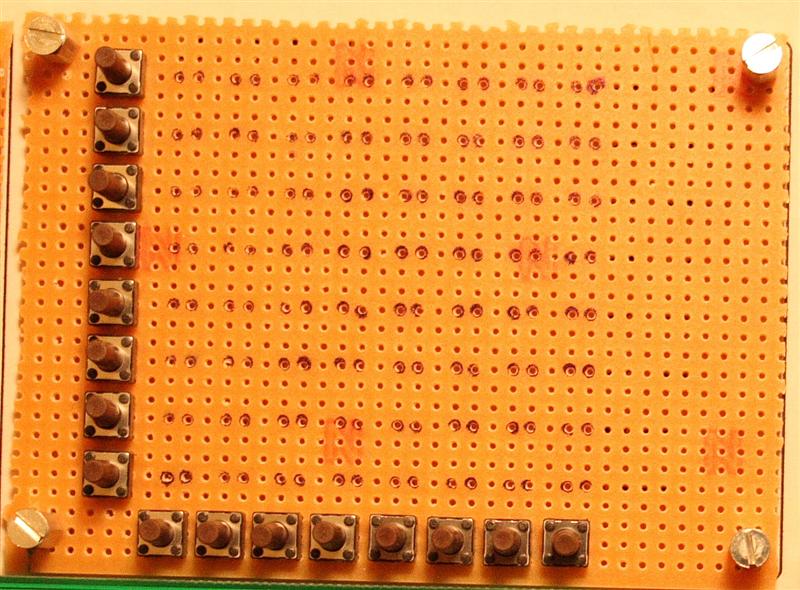
Hooked up all buttons and lights, they work!
The white LEDs were far brighter than the orange/red LEDs. To fix: 7.4k ohms (4.7k + 2.7k) seemed to lower the brightness enough to match.
05.25.2008
2-4pm I set up the compiler so I could add my 2 special buttons to the firmware. This is basically the same as TK's control surface, only with Wilba's address mappings. Here's what I had to change in the setup_mb6582.asm source code:
![]()
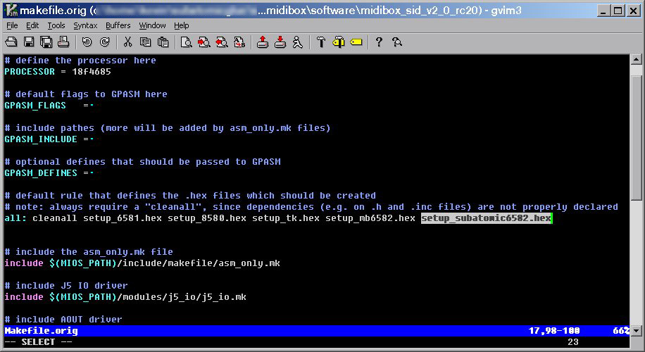
Slight tweak to setup_mb6582.asm to support my CC/PgUp and Edit/PgDwn buttons
Here's the final setup_subatomic6582.hex file for my midibox...
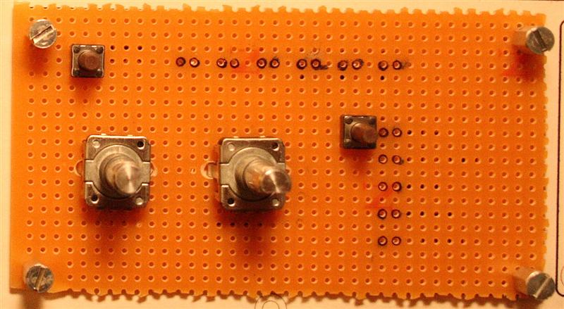
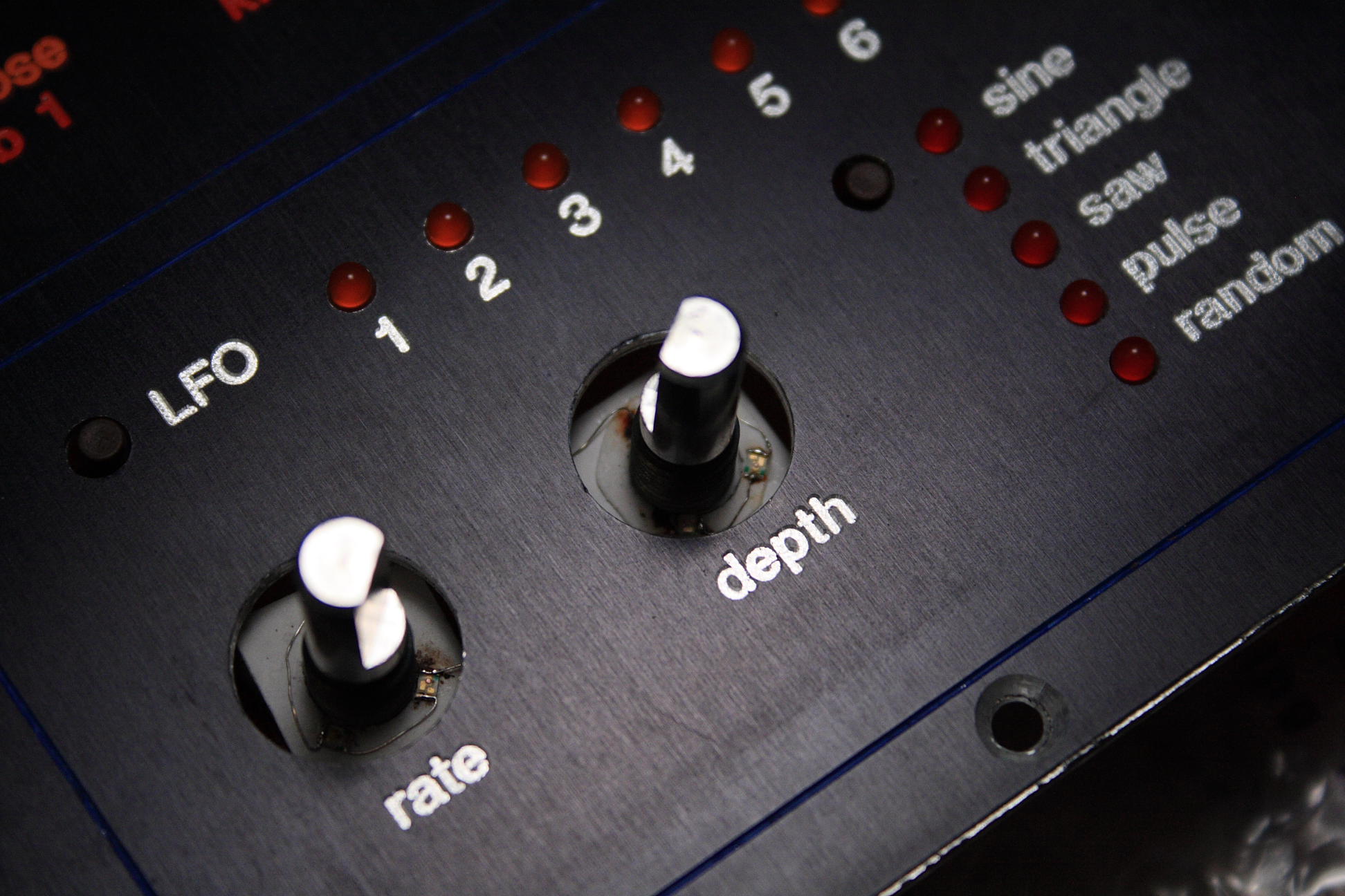
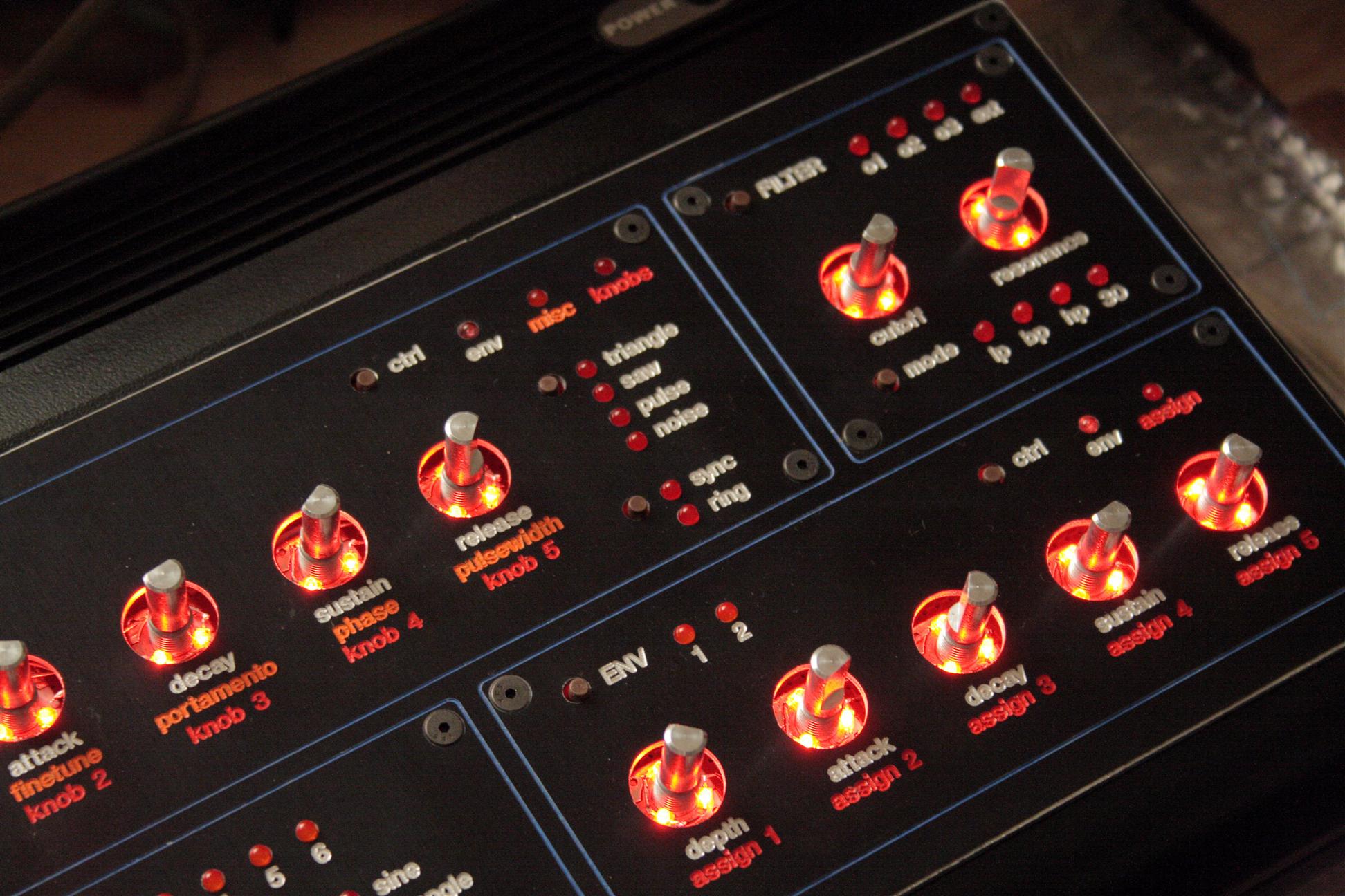
4-6pm hooked up all knobs.

Hooked up all knobs, they work!
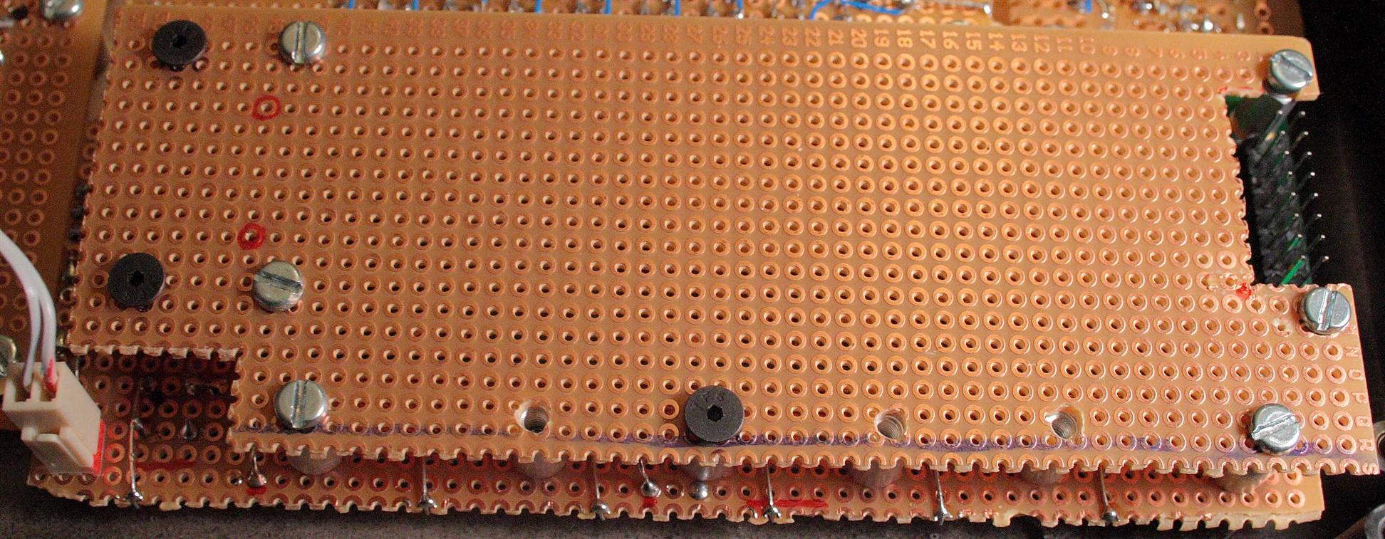
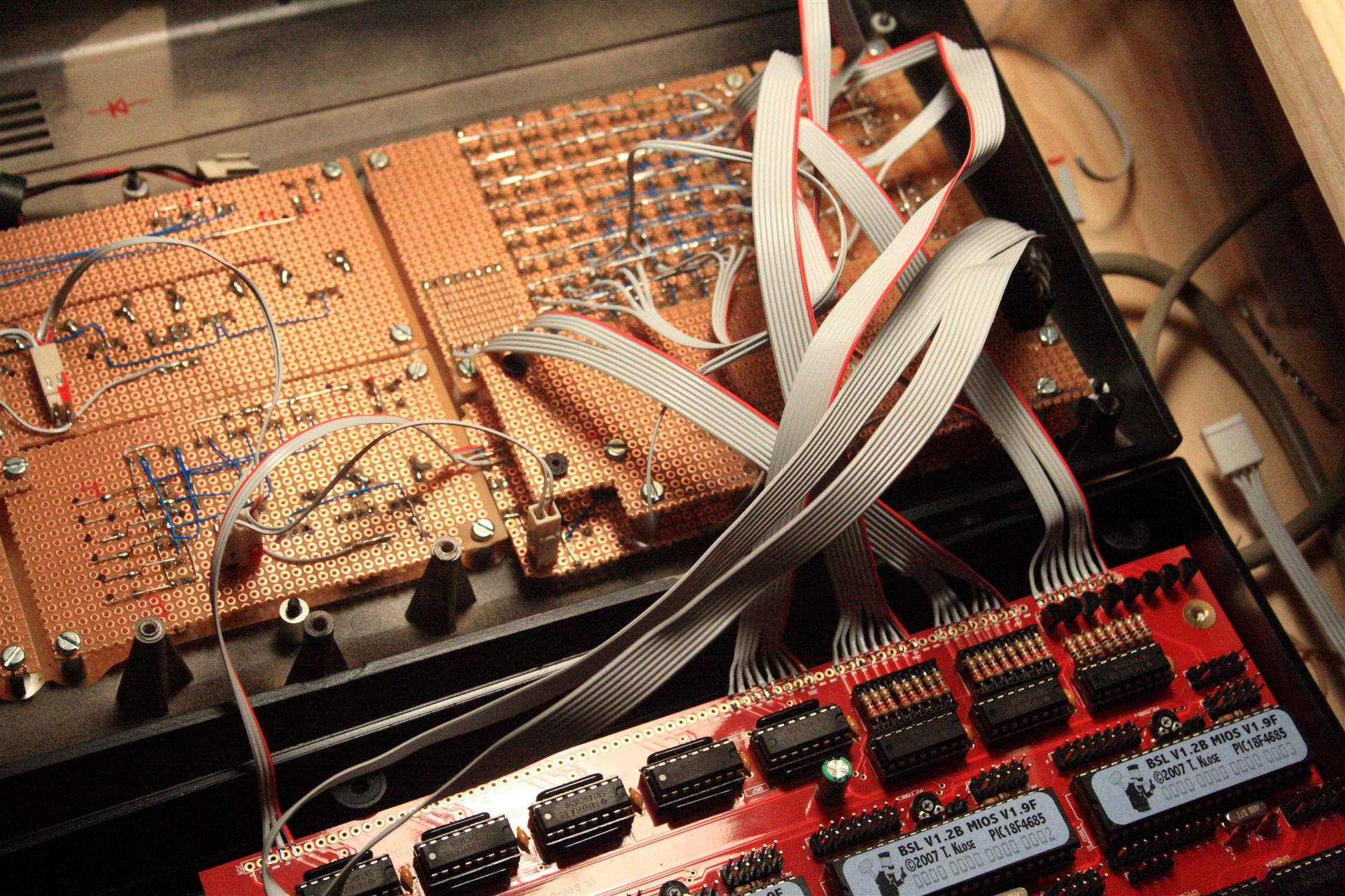
10-10:30pm cleaned up the wires a bit
Tied up the wires a bit...
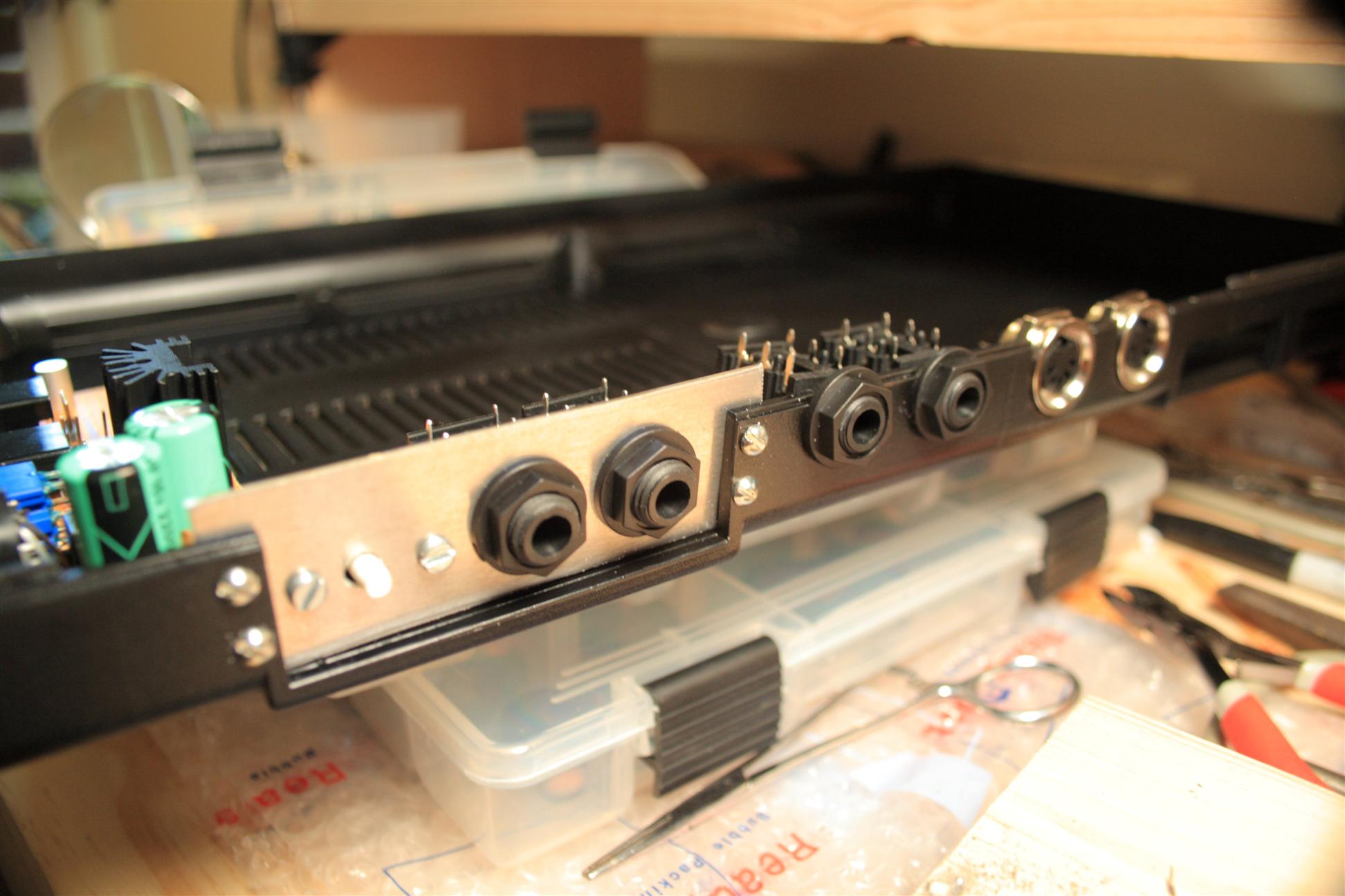
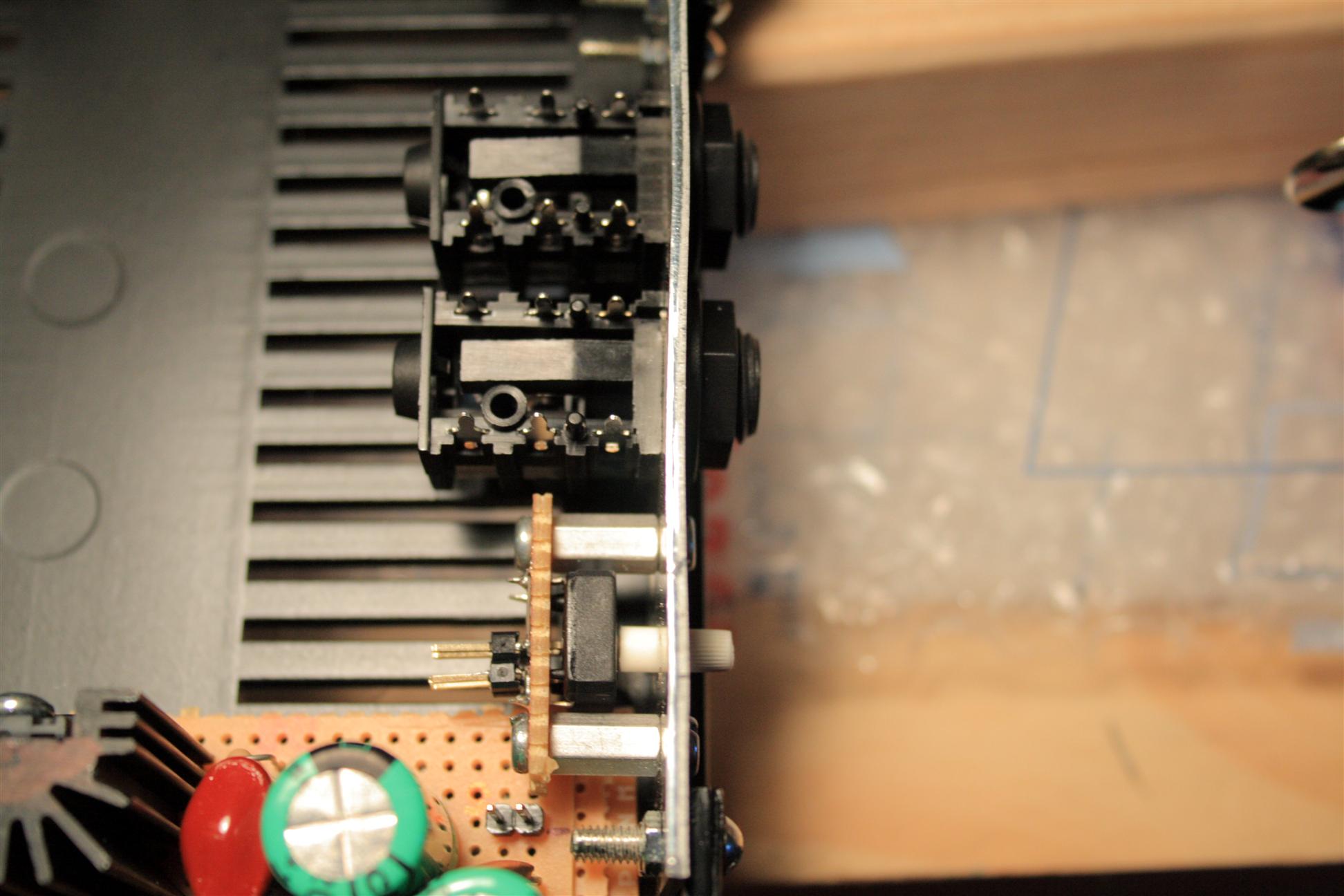
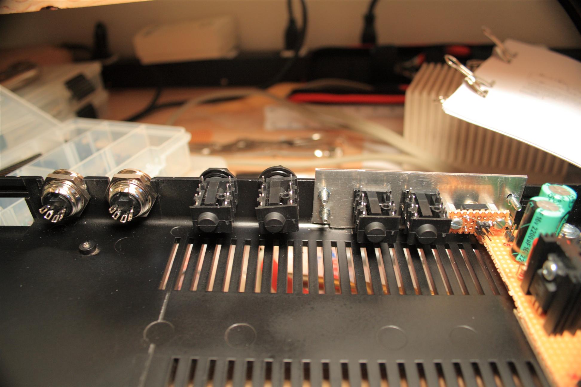
10:30-12:00pm Up until this point, I didn't have a mixed output on the case! Since we're wrapping up this project, it's time to mount the midiboxSID's output jack! So next I drilled the case for the output jacks. And then I added 2 of the 1/4" audio jacks so that connection to a mixer would be easy (most pro synths have 2 mono outputs for stereo)...
The "Left" jack is a stereo jack if nothing is plugged into the "Right" jack.
When the "Right" jack is plugged in, the right channel signal is automatically switched away from the Left jack over to the "Right" jack.
There are 3 ways to plug in:
- Mono (mono T/S jack plugged into the L jack)
- Stereo (stereo T/R/S jack plugged into L jack)
- Stereo (2 mono T/S jacks plugged into each of the L and R jacks)
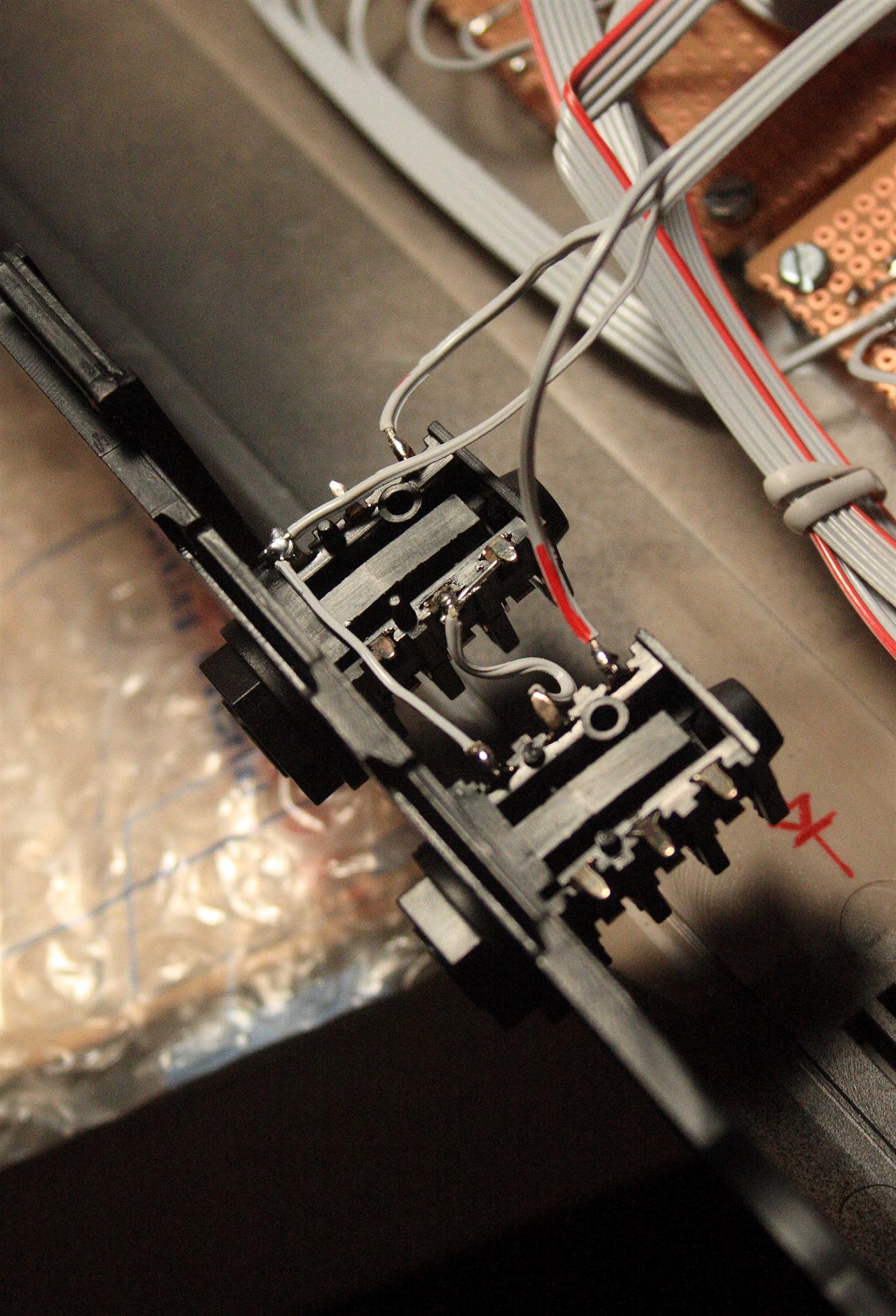
Added output jacks (L(mono/stereo): bottom right, R: top left),
these are switched to support one or 2 plugs for mono or stereo
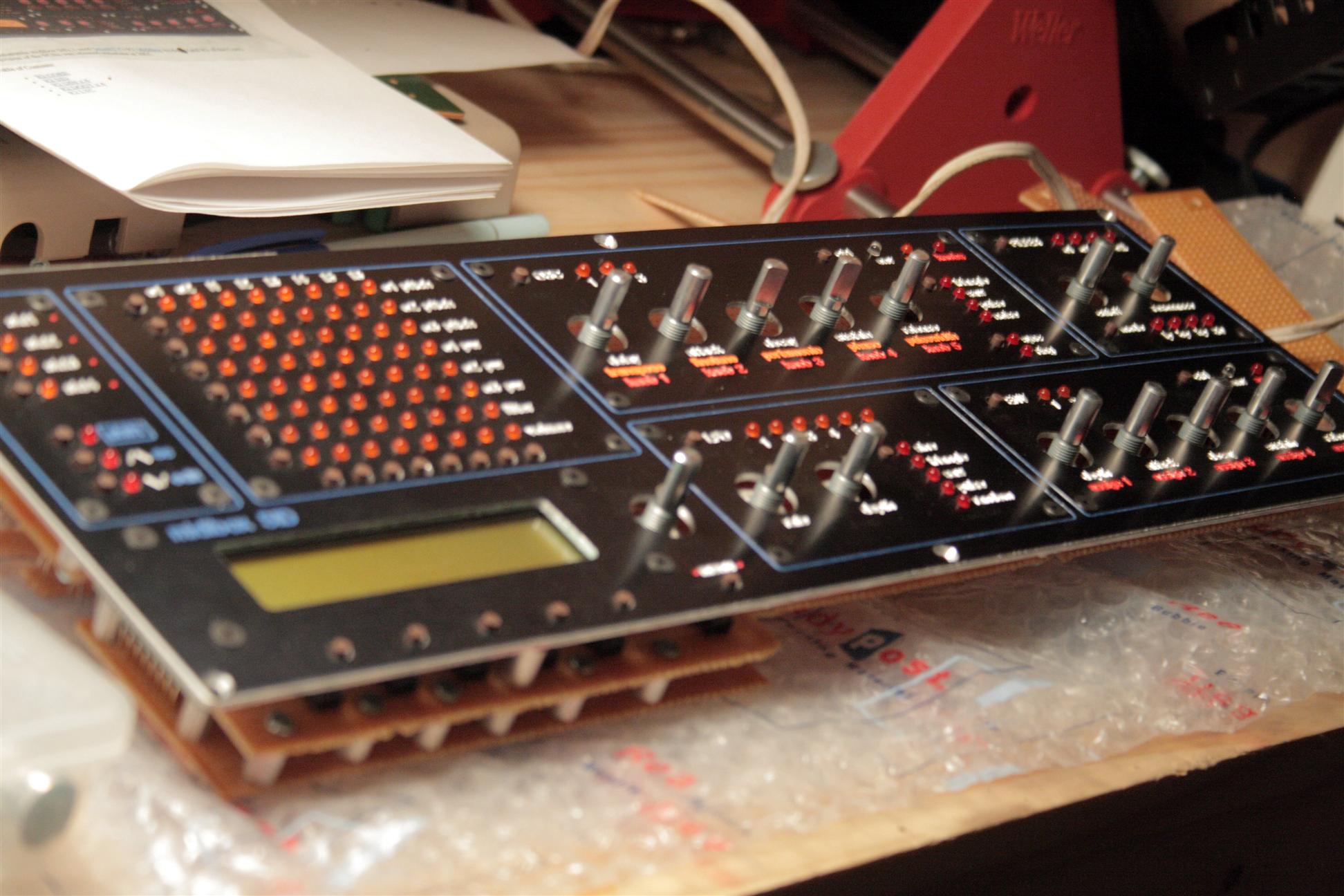
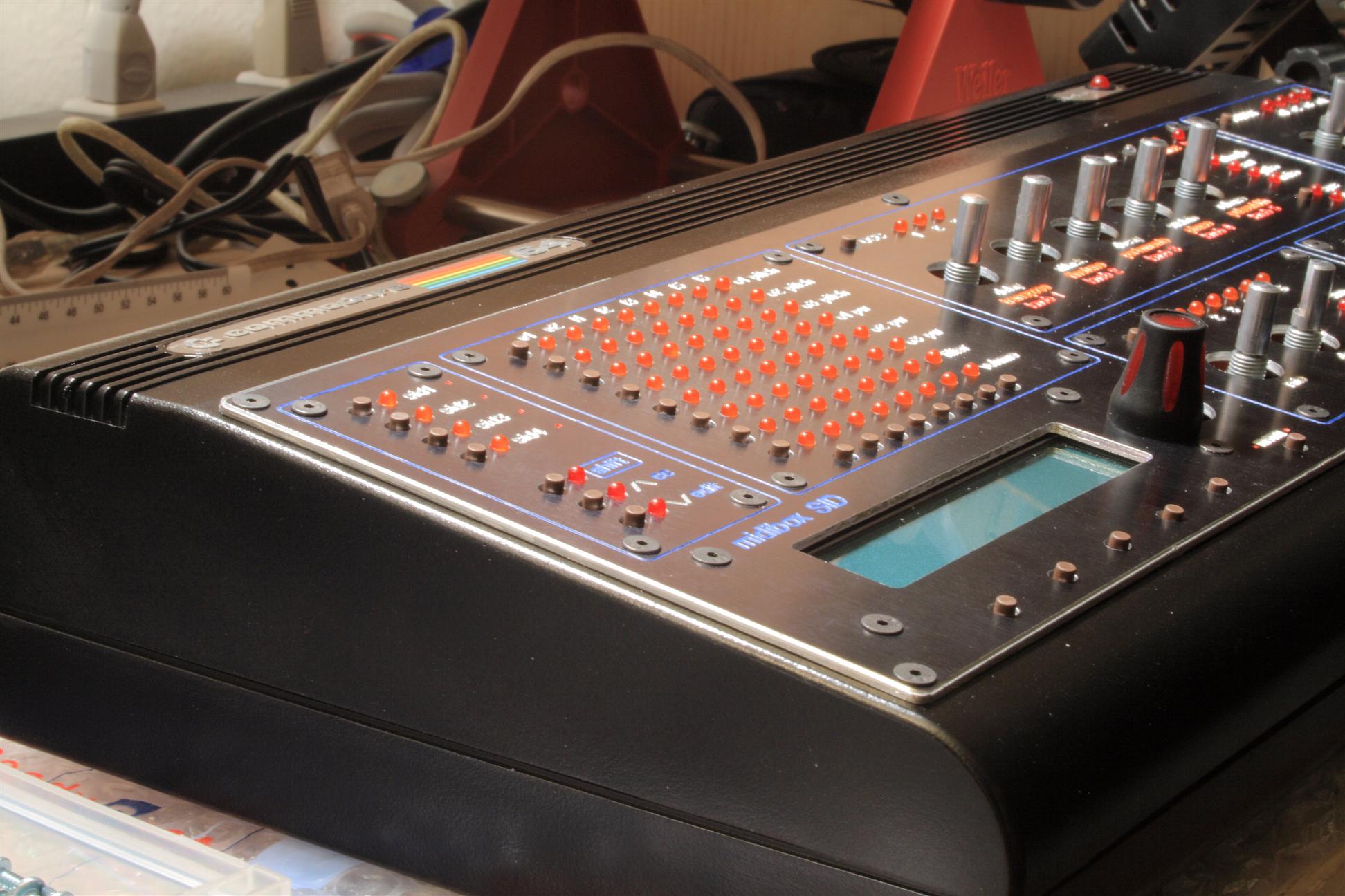
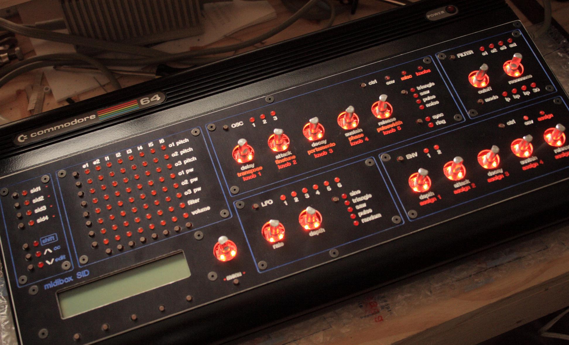
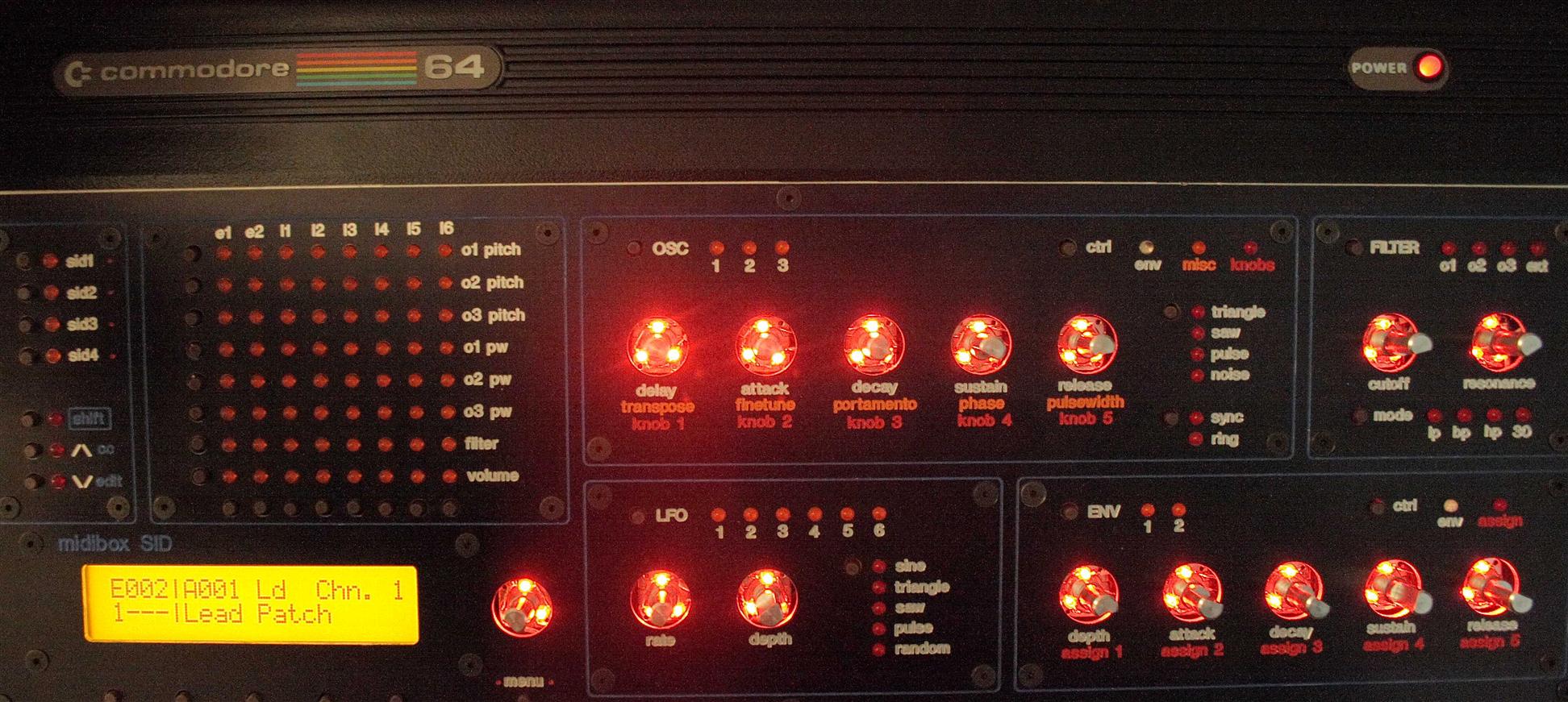
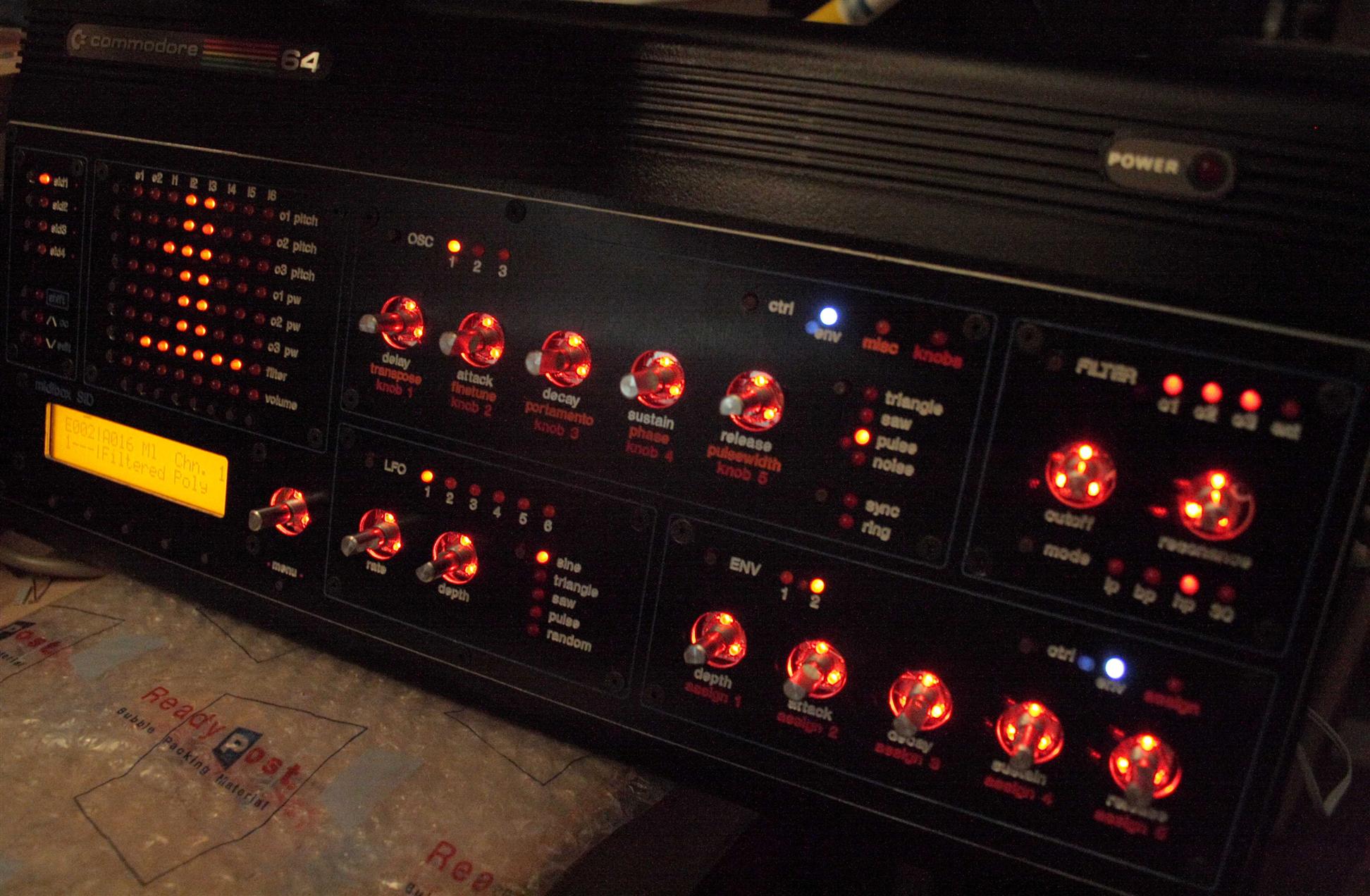
Ok, so I assembled the case, it's looking good, all aspects of the UI work
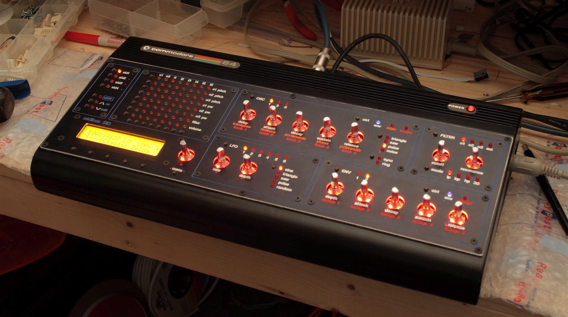
Looking good, Just need knobs now...
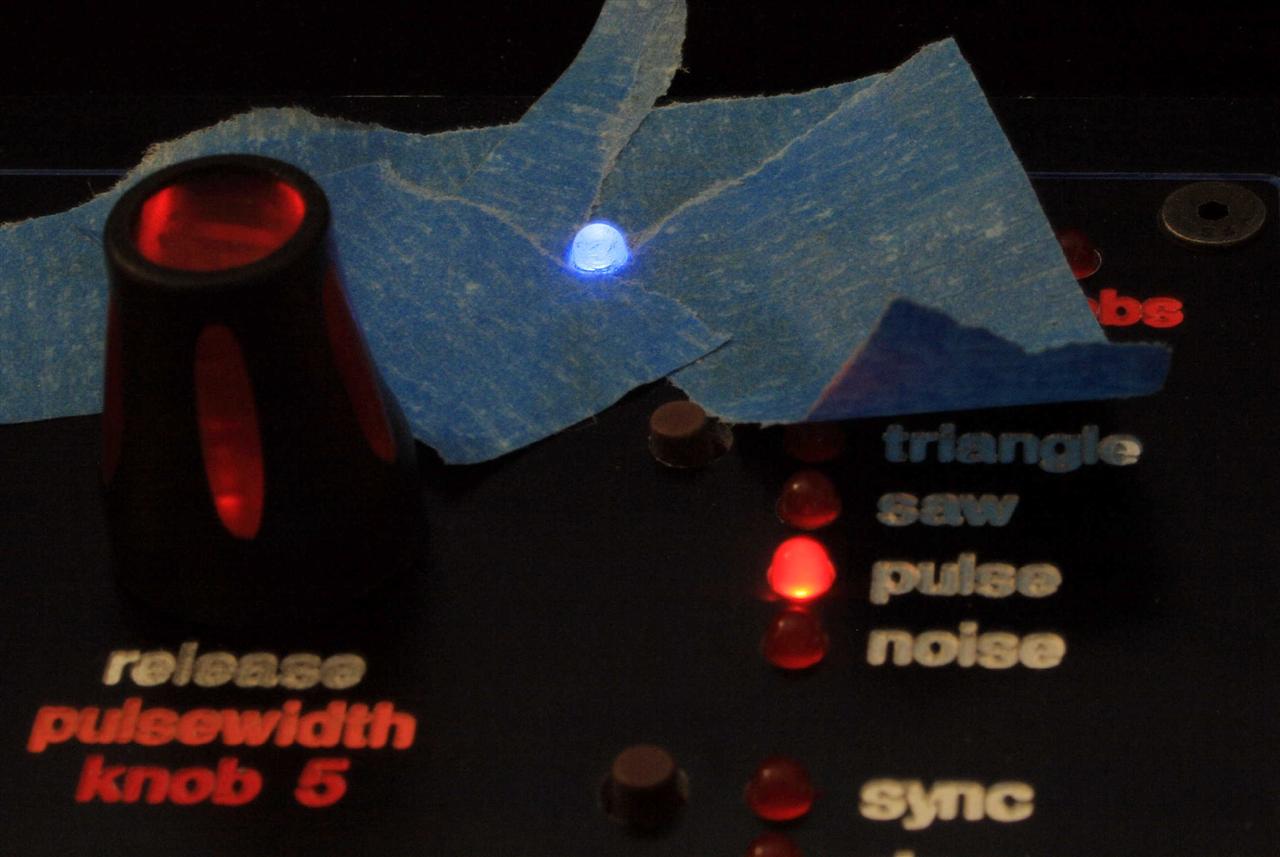
Before I add the knobs, I will first make little light-shields to keep the back lights from glaring out at you... tomorrow.
For now, enjoy some zelda on the SID...
![]() zelda-c64.mp3
zelda-c64.mp3
05.26.2008
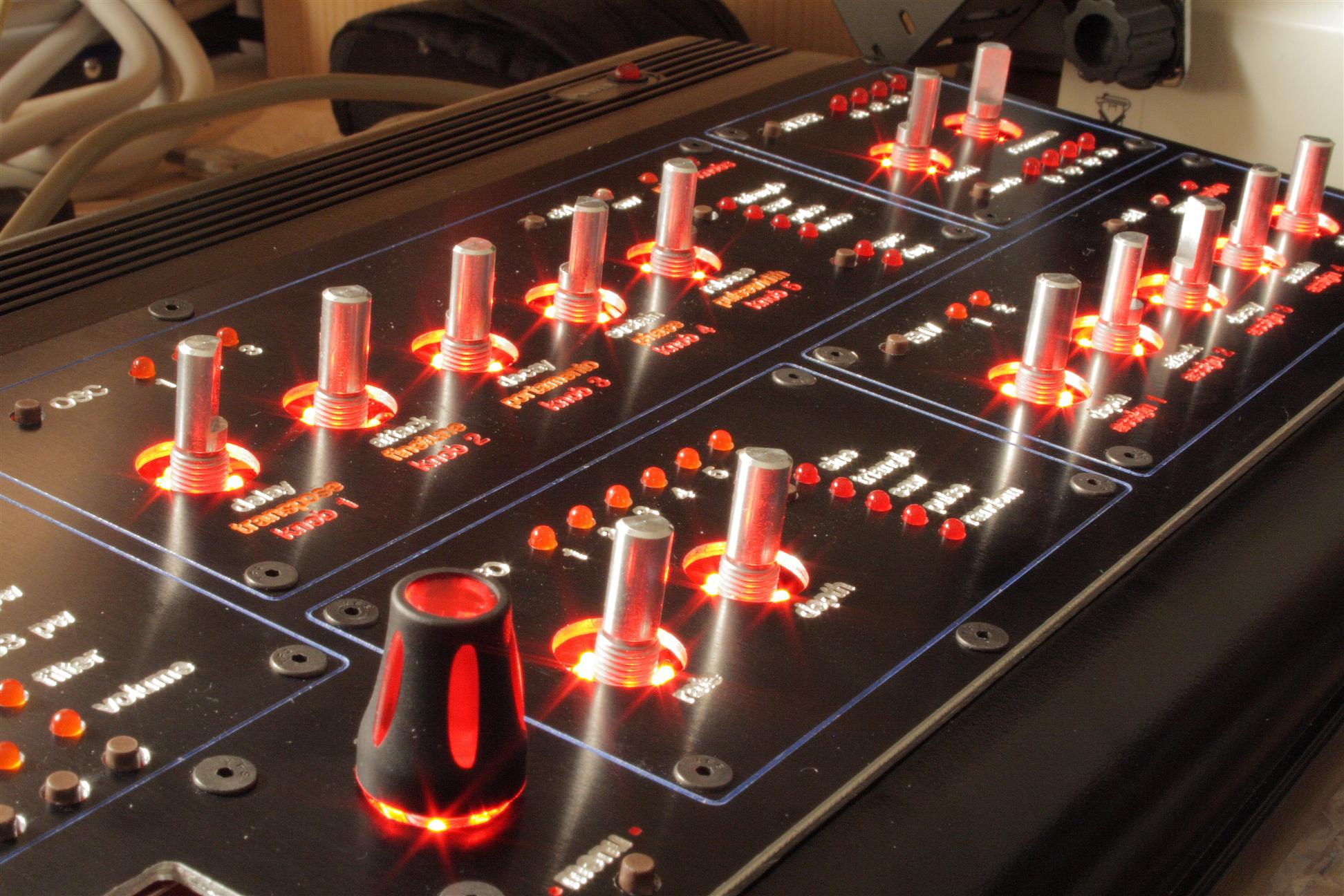
12am-5pm I finished the MidiboxSID today. First I needed to add the knobs, but before I could do that, I needed to do something about the back lighting spilling out from under the knob. I solved this with little paper rings beneath each knob. This took a lot of time to cut out and fit but the effect is worth it. I cut the rings to be flush against the encoder surface, and I cut notches into the ring to fit over each wire leading away from the backlight leds.
Cutting black construction paper to be used as rings to block the backlighting from spilling out under the knobs
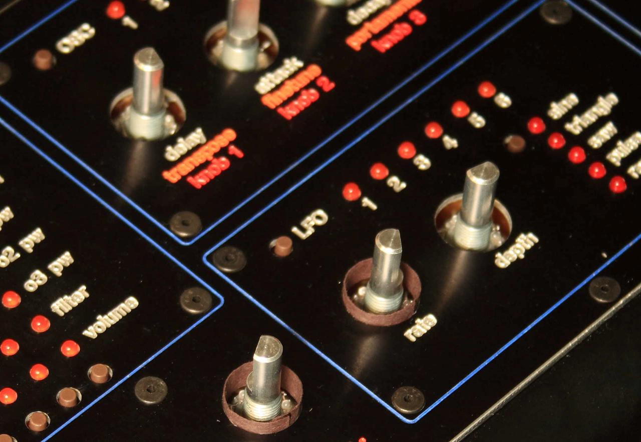
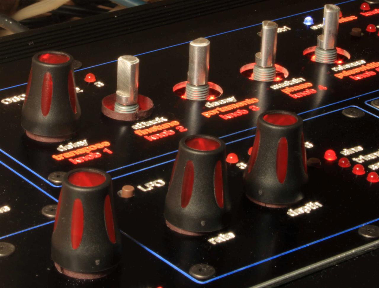
Attaching paper rings under each knob, and (finally!) adding knobs
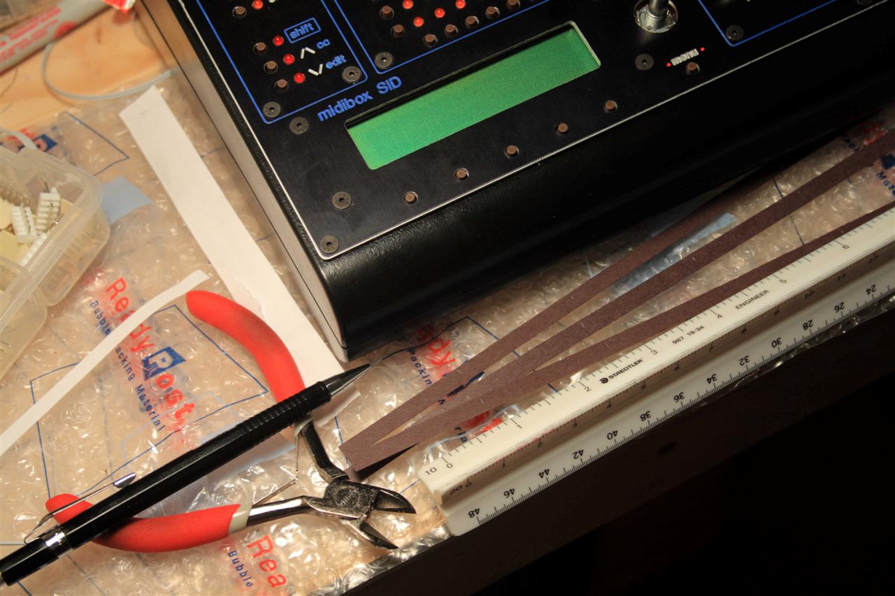
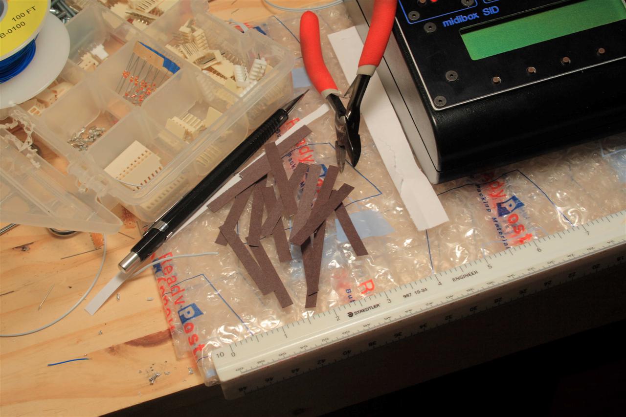
One last cosmetic thing to do, make the white LEDs "diffuse" instead of clear, this way you get a wider viewing angle (they look better and match the other red/orange LEDs).
Making the white water-clear LEDs into diffuse - fine grit sandpaper
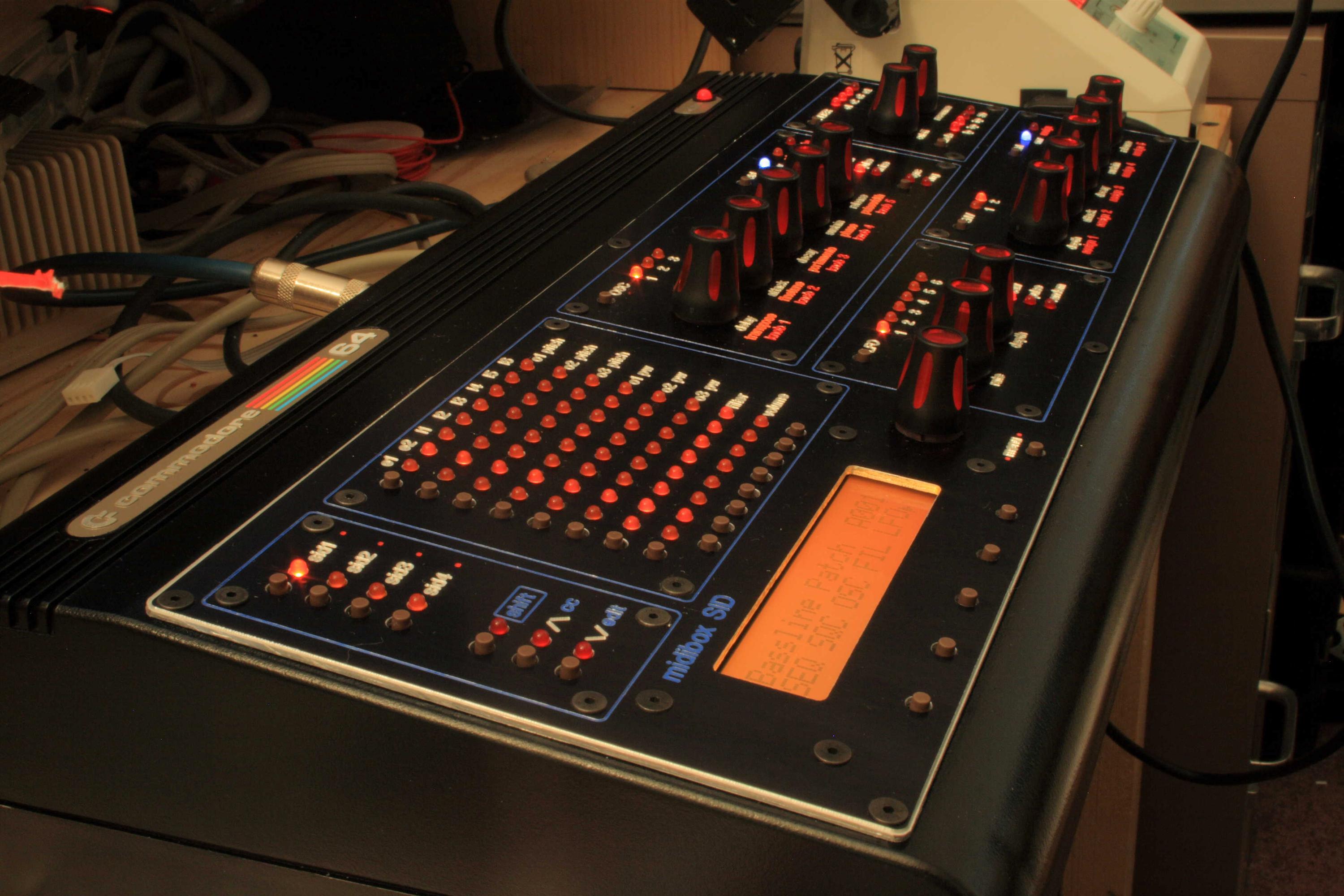
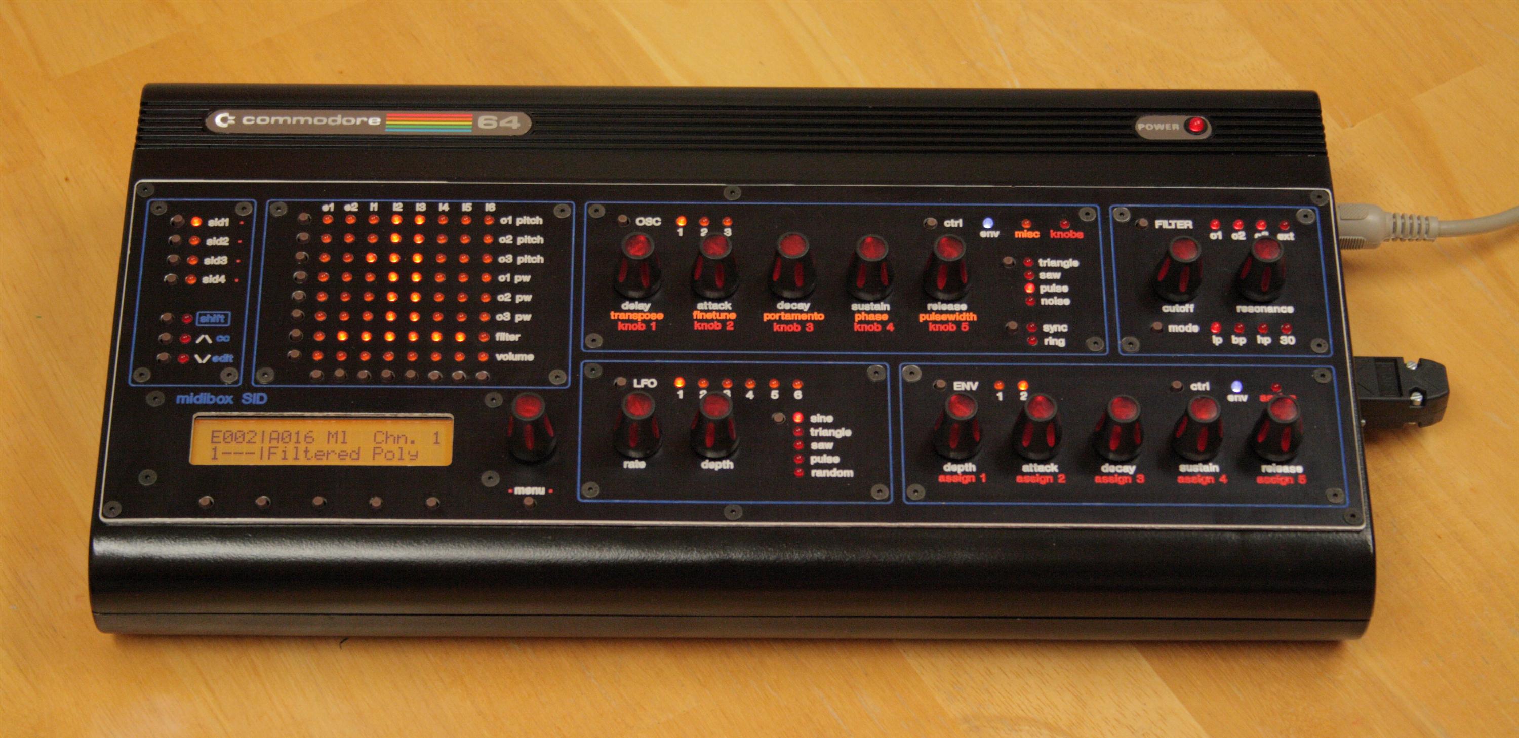
Done!
Here's some goofing around I did in bassline mode (it has a step sequencer built in!):
![]() mbsid-bassline.mp3 (with drums and fx)
mbsid-bassline.mp3 (with drums and fx)
![]() mbsid-bassline-dry.mp3 (dry SID sound - no processing, no drums)
mbsid-bassline-dry.mp3 (dry SID sound - no processing, no drums)
![]() mbsid-psytrance.mp3 (with drums and fx)
mbsid-psytrance.mp3 (with drums and fx)
![]() mbsid-psytrance-dry.mp3 (dry SID sound - no processing, no drums)
mbsid-psytrance-dry.mp3 (dry SID sound - no processing, no drums)
05.31.2008
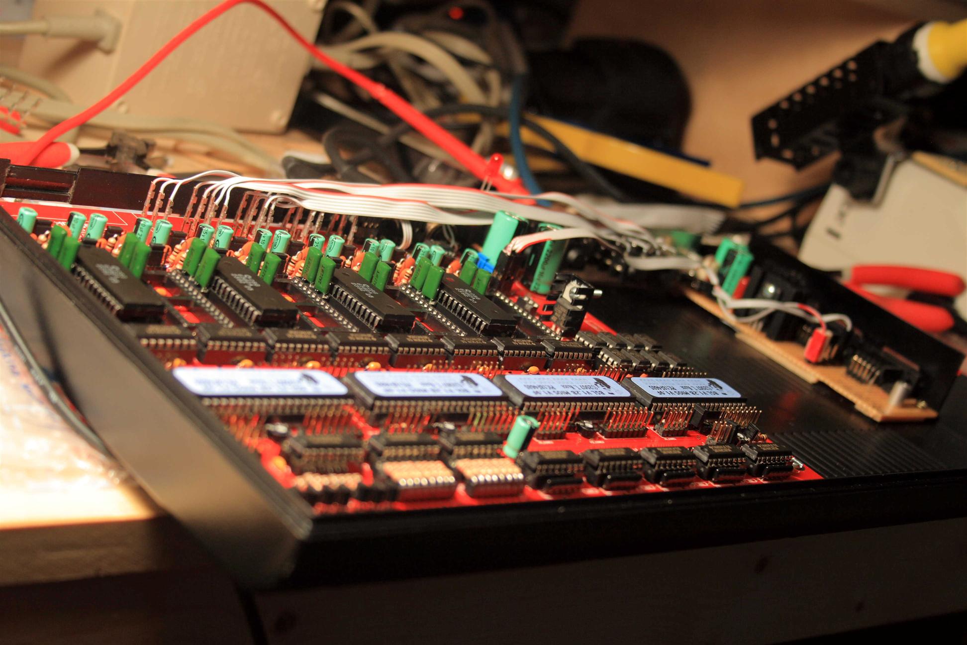
12midnight Power problem solved, 8xSIDs working!
Got a new PSU off eBay, I can now run all 8 SID chips. The beige brick PSU I had only supplies enough current for a 4xSID monosynth, which you see above (probably because it's old/wornout/broken... no idea)
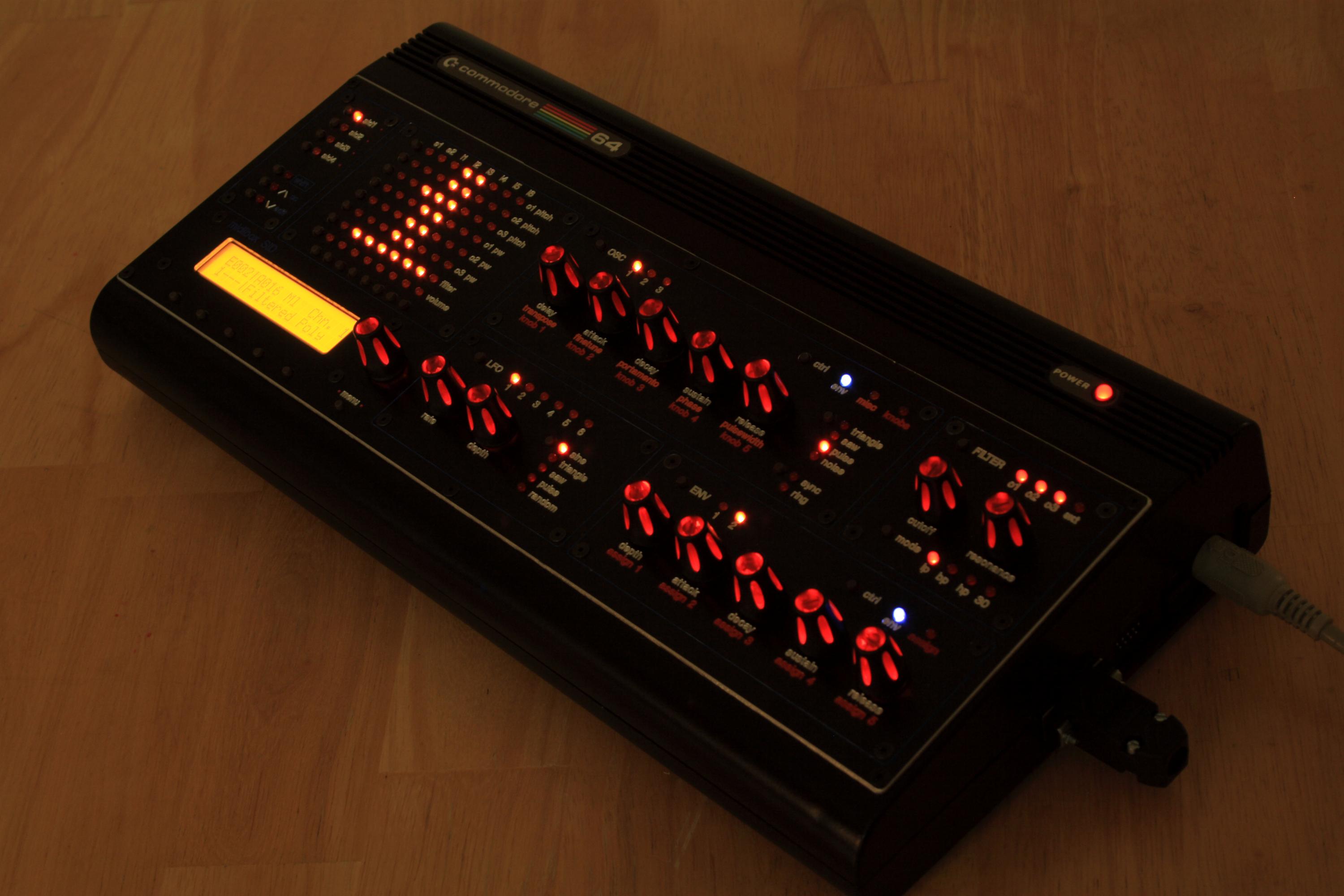
We now have a stereo MidiboxSID!
![]() mbsid-presets-stereo.mp3 - Dry (no fx) Stereo SIDs - All 128 MidiboxSID presets
mbsid-presets-stereo.mp3 - Dry (no fx) Stereo SIDs - All 128 MidiboxSID presets
![]() mbsid-bassline-stereo.mp3 - Dry (no fx) Stereo SIDs - Bassline mode
mbsid-bassline-stereo.mp3 - Dry (no fx) Stereo SIDs - Bassline mode

8 SIDs stuffed and working!
Conclusion
This project is by far the most advanced I've built. The custom case, the custom panel design and fabrication, the parts sourcing, the control surface module fabrication and wiring, the power supply, changing and recompiling firmware, knob backlighting, etc... I didn't make this project easy on myself. I started with a challenging design and didn't compromise. And with this many customizations there's an equal number of documents (and more) to read, and understand and apply, from the midibox uCapps website. Certainly with Wilba's mb6582 board this project was a lot more straight forward than it could have been. I definitely found a few good people to help with some of the key areas here, CNC work by SteveM, acquiring the c64 computer from Ceedub, SID chips from Wilba, and PCBs and parts kit from SmashTV and Wilba. Without this help, I'd still be working on this.
It's a damn cool synth, for sure. It can be very chippy (check out zelda.mp3), on the other hand you can make fat 202-like basslines (almost 303-like), juno 60 style growly synths, and manipulate the filter like on modern subtractive synthesizers. The SID scales really well to modern day music! In addition, the synth has a bassline mode with a step sequencer build in, one per SID, how cool.
![]()

![]()
Done!
Thanks
Thanks to Wilba and TK:
I'm very impressed with these two people. TK created a great synth, and Wilba streamlined it into something simple yet very powerful. These people rock, and need congratulations. In addition, Wilba was a lot of help on several issues I had along the way. He's definitely a great asset to DIY synth building.
Thanks to Groupbuys, Wilba & SmashTV:
SmashTV makes this project a lot more accessable to a lot more people, and he certainly saved me a lot of effort and time with the BasePCB and Parts he sold me. Wilba's 6582 SID group buy is also much appreciated.
Thanks to Steve M:
SteveM "printed" my panel on his homebrew CNC device, and made one for himself. Many thanks goes to Steve for helping out. I hope he builds his synth, then mine will have a twin. :)
Thanks to CeeDub:
Ceedub (from the x0xb0x forums) turned me onto this project back in 2005 and donated a C64 and modules to help me build it. Awesome stuff, I owe Chris something now I'm sure.
Future Work
TODO:
- get external bank stick port hooked up to something inside
- add feedback pots
   (500k dual gang pots wilba has on the back of his mb6582 box).
Links
- midibox SID
- midibox 6582 (midibox sid made simpler)
- albs.de (source for the 'waldorf' knobs)
- schaeffer (custom panels)
- crystalfontz (LCDs)