x0xb0x worklog
|
I built x0xb0x #121. A
"x0xb0x" is a clone of the classic Roland TB-303 synthesizer.
There is a good historical
video on the TB303 if you want some background info. On these pages is a worklog created as I built the synth. - Listen to x0xb0x #121 naked [mp3] - Listen to x0xb0x #121 processed [mp3] - Hear a longer x0x jam session [mp3] - Impatient? Jump ahead to the construction. - Mods... Jump to modifications....
UPDATE[1.22.2006] We're on synthtopia, cool! |
Tues 10.25.2005
6:30pm I happened to be home sick today. Tracking info at the fedex website said the x0x was "on the truck" at 6:30am. After waiting all day, the box of x0x arrived at the front door. I unpacked to look at what's inside, doing a fast check for any damages and all looks good. Packed very well. I also ordered the USB x0x interface to be pre soldered from adafruit, and that appears to have been seldered well.
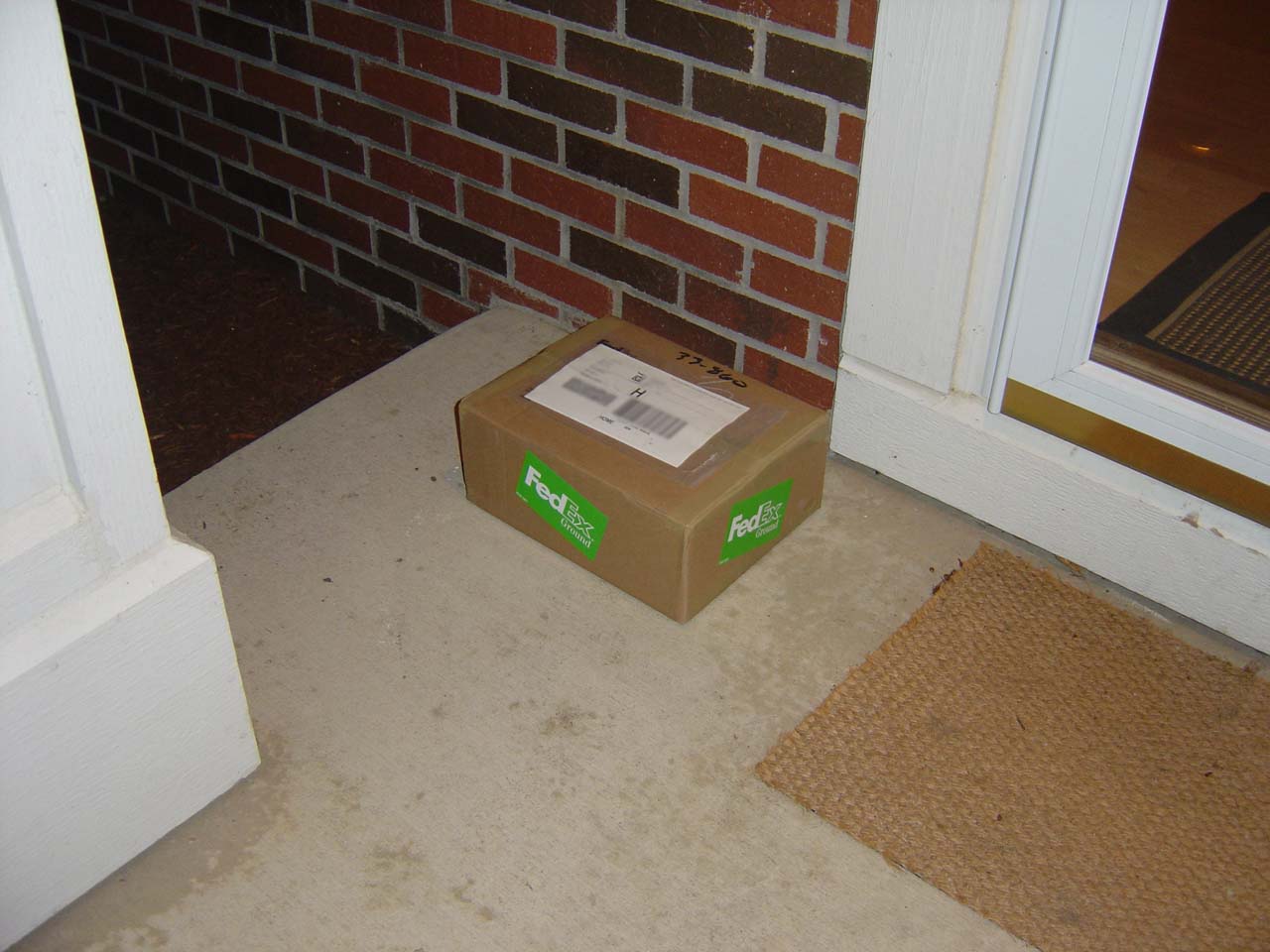
x0x was "on the truck" at 6:30am. After waiting all day it arrived at 6:30pm, woowoo!
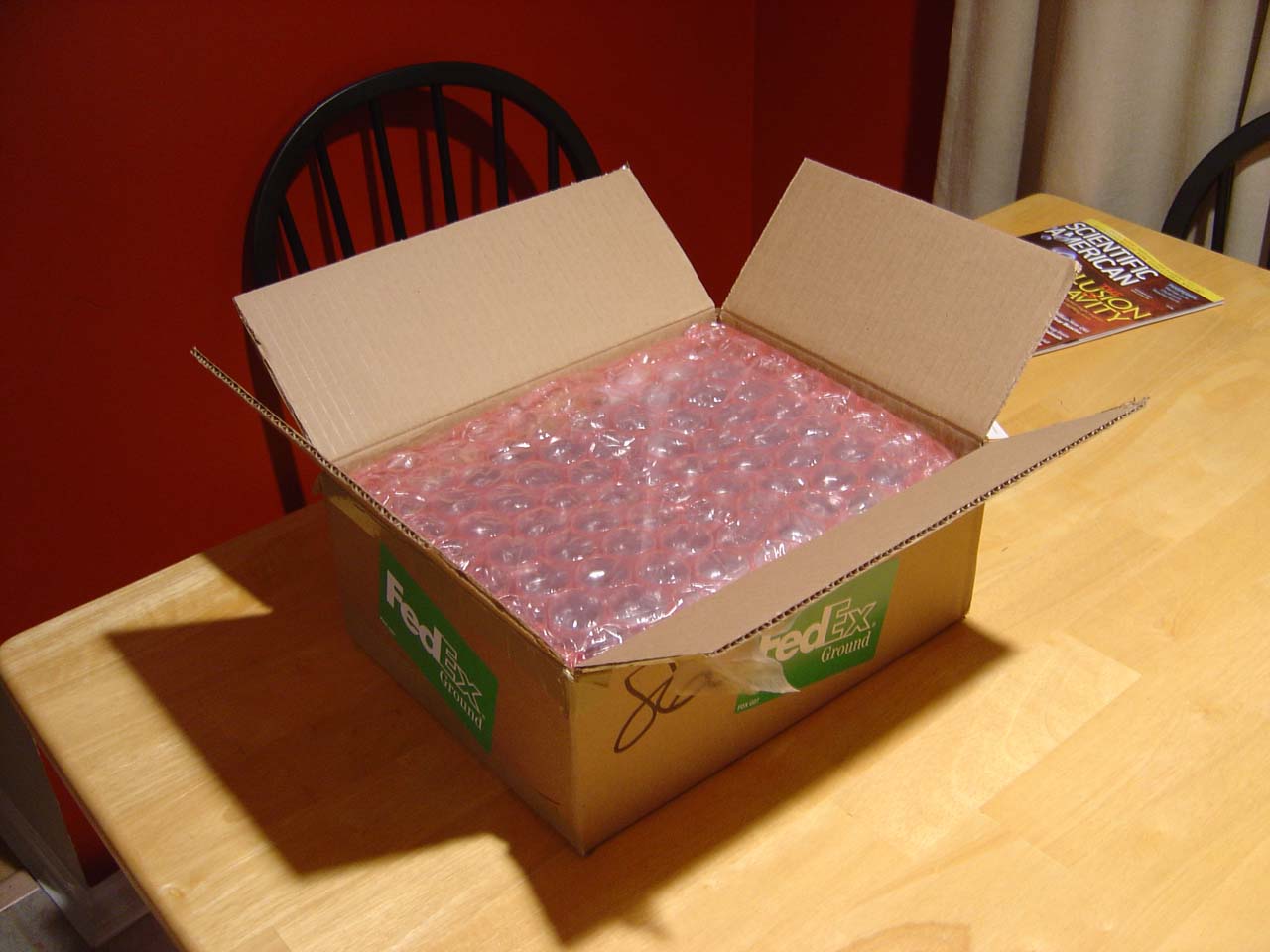
Tight pack job, bubble wrap goes all the way around
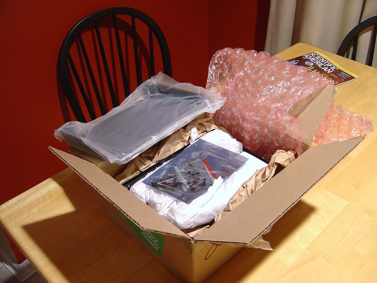
1st thing I see, some parts are stuffed inside the hard x0x project case.

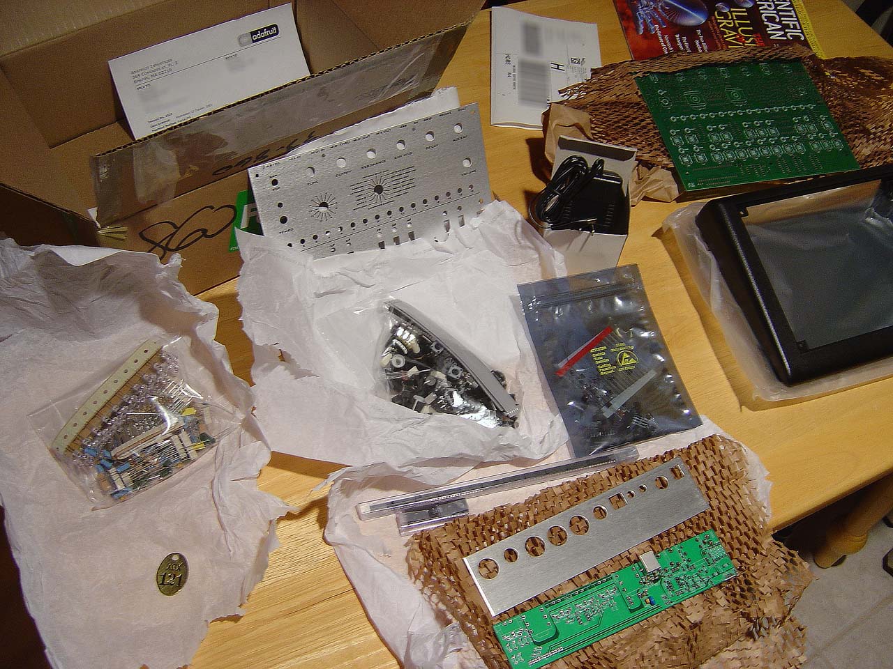
unpack it all, this is it...
found the gold tag (plus the invoice) at the very bottom of the box in a sealed envelope.
Wed 10.26.2005
7:30am - 9:30am Printed current manuals, fab, user, mods, schematics. Chopped images and edited HTML to make nice books. This project is very well documented. Also ordered from mouser 100 of the 733p transistors ($6) so I can try to find one with a high beta (to more closely match the now-extinct 733ap part from the original 303). Got the tip about the 733 from the x0x mods page.
UPDATE 8.10.2006: I've done tests with beta 250 up to beta 400, and there is a difference, read the analysis

printed manuals. I used 4 8x10's for the schematics, booklet printing for fab manual, mods, and userguide
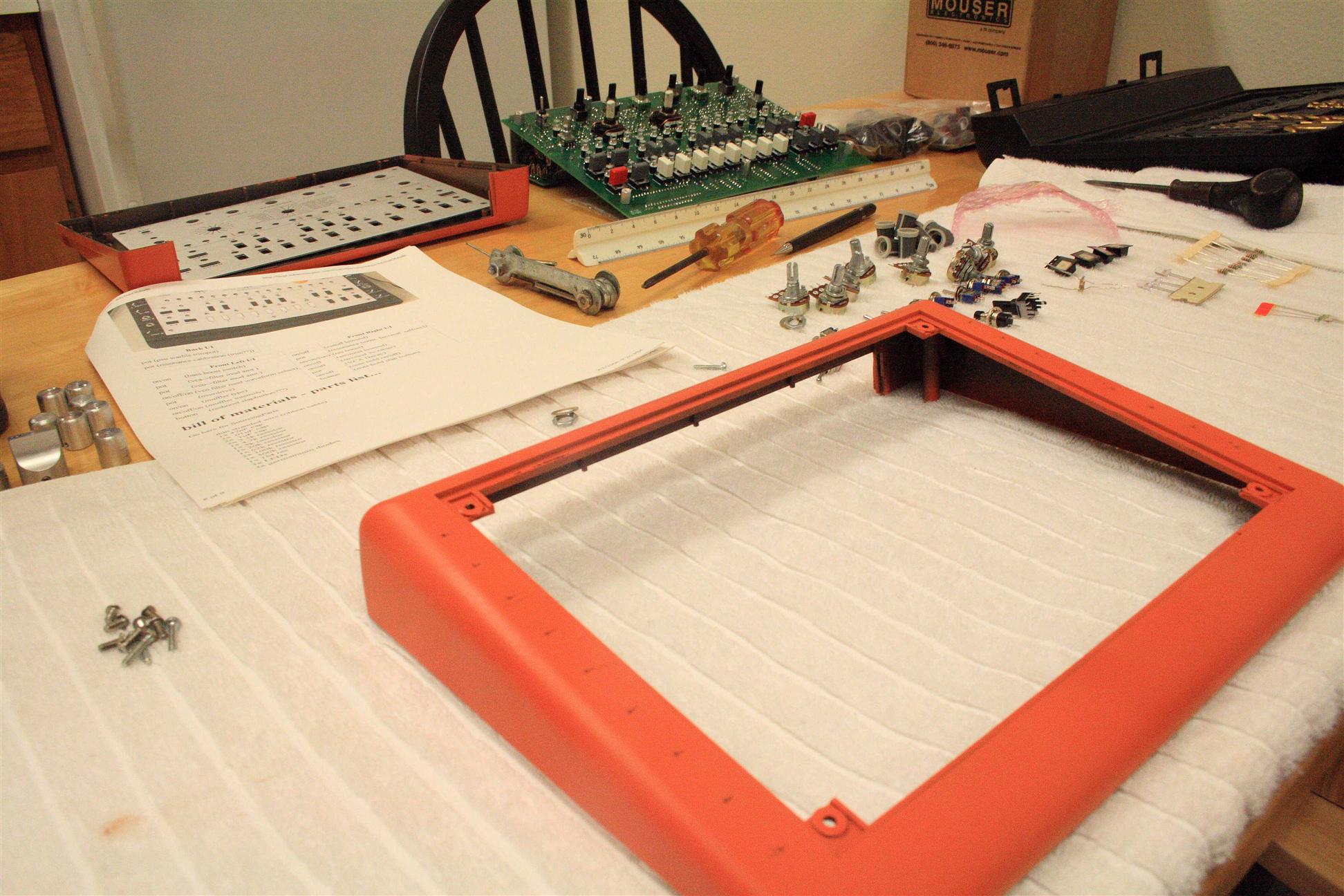
8:30pm - 10:30pm Unpacked first Bag-o-Parts (pots, knobs, bulky stuff), Organized these into 2 tackle boxes (Plano model #1354-20). All parts accounted for and present, incl. the extra detented pot I ordered (for tuning knob). Still not sure if I'll use that. Documented all numbers/names on parts (like pots) in case I ever want to order more for other projects, I wrote these next to the part in the bill of materials (BOM). Unpacked the second Bag-o-Parts (caps, thermistors, resistors, LEDs), started taping resistors to a sheet of paper and writing resistor values next to each kind.
unpacked 1st bag, big pile of knobs and buttons. starting to process.
1st bag processed, 2 bags to go!
halfway through the 2nd bag, will resume tomorrow
Thurs 10.27.2005
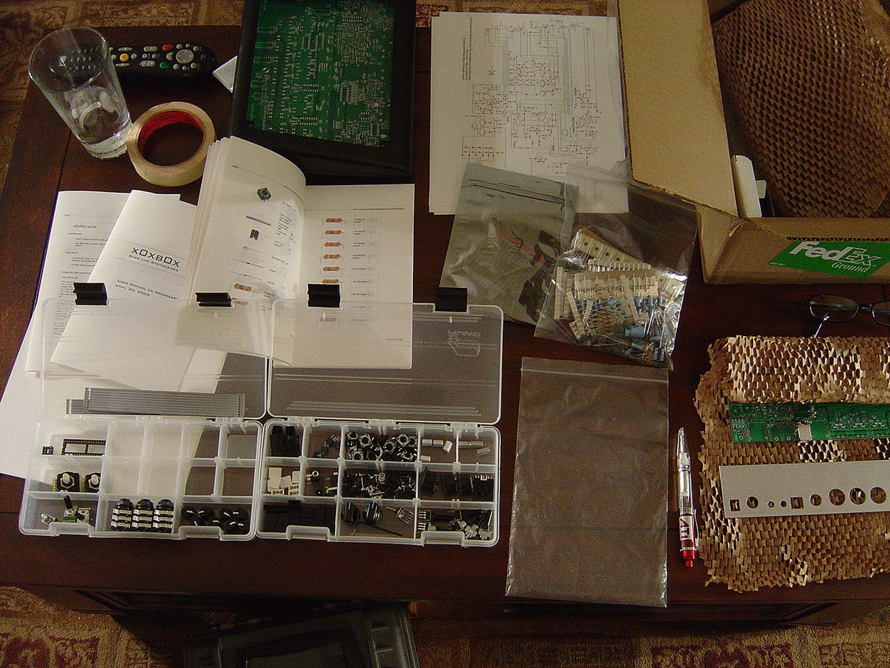
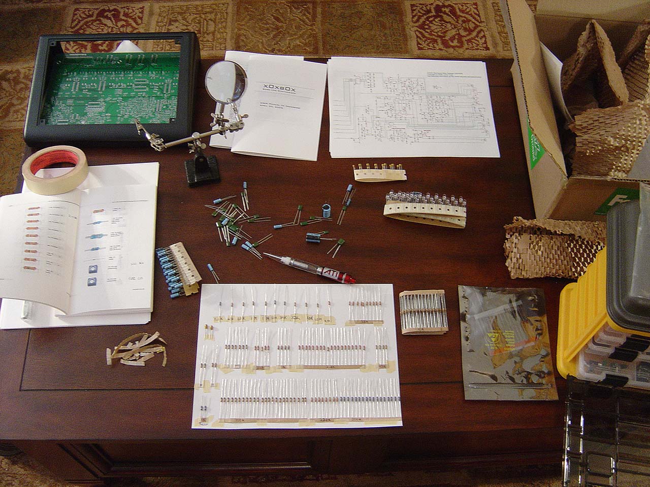
7:30am - 9:15am Finished unpacking/cataloging the second Bag-o-Parts (caps, thermistors, resistors, LEDs), used 2 pieces of paper total on this bag, everything is taped and labeled with their ohm/farad/volts/partnumber values� Resistors are a huge pain in the ass, or I need to learn to correlate colors to numbers, luckily I could compare them to the pictures (again adafruit rocks for including a picture of every single part in the BOM). All parts in bag 2 accounted for! At this point we have 2 full sheets of paper (caps/resistors), and 2 full tackle boxes (knobs/pots/buttons). I have to say I�m impressed with the accuracy so far, nothing extra or missing.

finished processing 2nd bag, everything's looking very... organized.
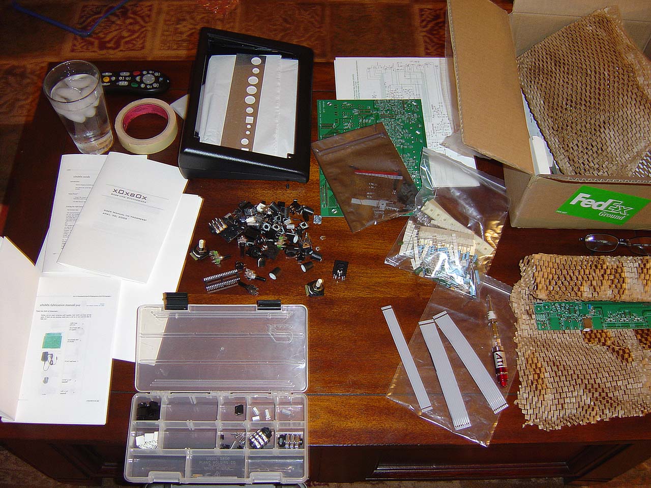
7:30pm - 10:20pm Unpacked the 3rd and final Bag-o-Parts (transistors/etc..). Added everyting to a piece of paper, left the bulky IC chips in their static tube though. Everything is accounted for. This concludes the inventory of parts. So now all parts of the x0xb0x is organized for fast finding (see pictures) either on paper or in tackle boxes. This will help me 1.) not lose stuff, since it's all taped down or in a box, 2.) find stuff fast and 3.) accurately during soldering. I'm amazed at the great pack job from the adafruit people. Next I suppose I could test all the parts, we'll see.

unpacked 3rd bag, big pile of transistors, empty paper
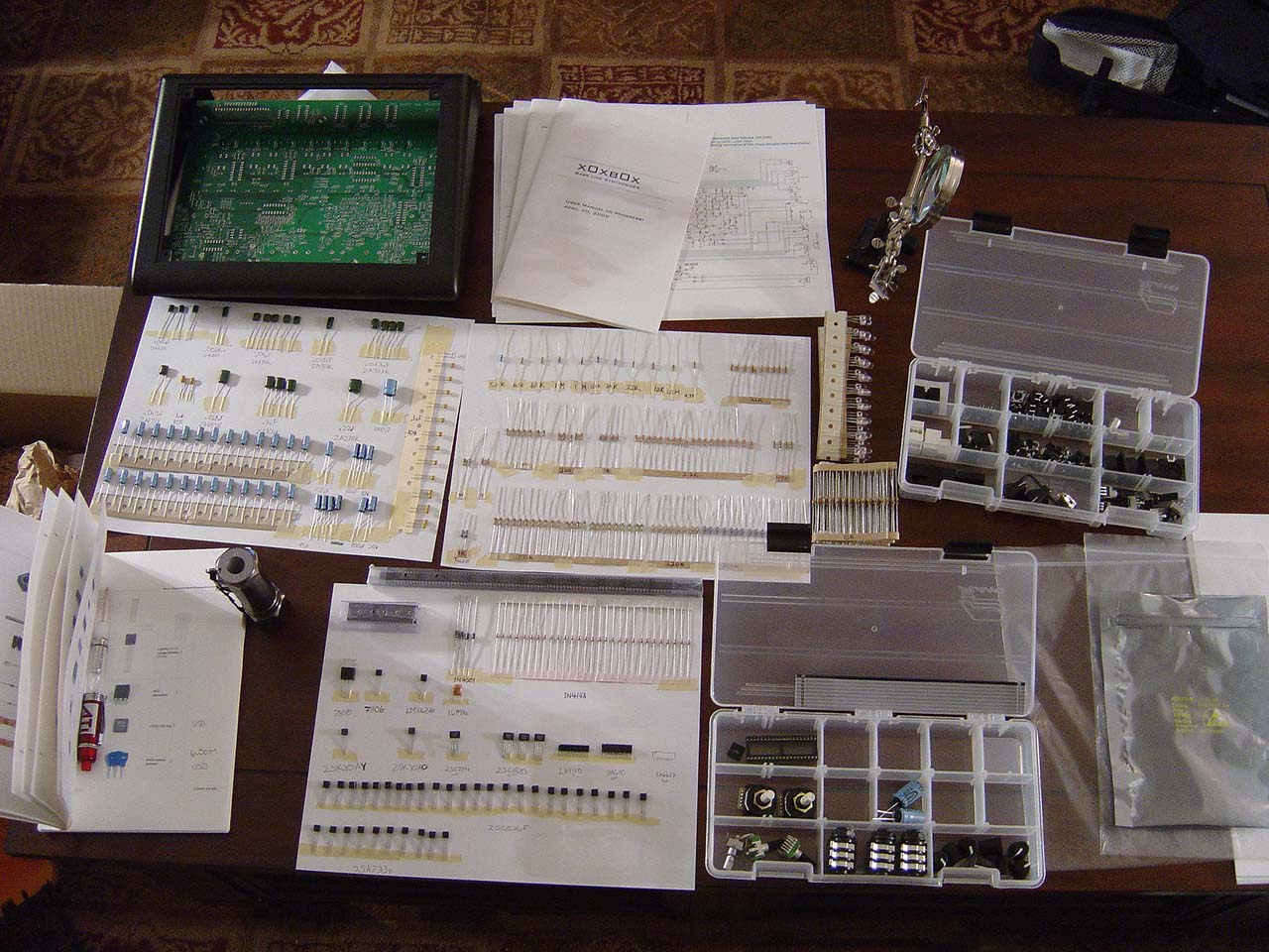
3rd (and last) bag added to the piece of paper, all parts present! you're looking at the full x0xb0x splayed out like roadkill. yes, highly organized roadkill
Monday 10.30.2005
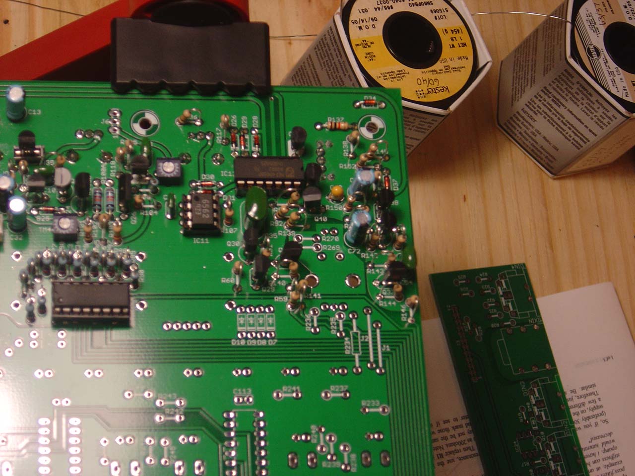
11pm-12am The 100 2sa733p transistors I ordered from mouser.com arrived. Tested each one for beta. Apparently the original tb303 had 2sa733pa's which had a higher beta than the 2sa733p. Because of quality diffences between transistors the beta varies from component to component. So out of the 100, they vary wildly within about 240hfe to 350hfe. I was able to find a few that came close to the 733pa's beta of "300 or higher" - 353, 338, and several 326's, wheee, hope it was worth the $6 and hour of time. This is supposed to help the x0xb0x match "the more pronounced resonance" of the tb303.
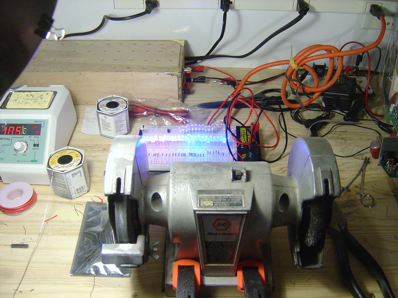
The Kester 63/37 solder arrived today as well. It has a lower melting point and a faster state change than other solders (narrower band of temperature range for liquid to solid transistion), so should be easier to work with than the recommended 60/40 solder. 63/37 changes from liquid to solid in a 0deg band (instantly) while 60/40 has a 13deg band where it is pasty before solidifying...
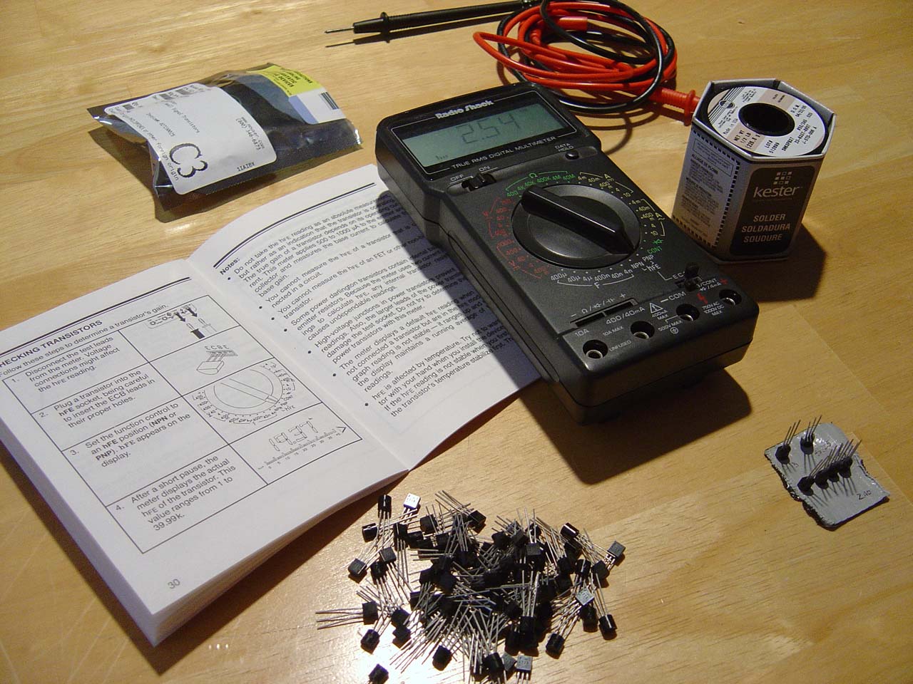
checking 2sa733p's for a high beta to match the 733pa's in the original tb303
NOTE: something's wonky with my multimeter's hfe measurement. It's stable, but it's n (where n = x / 100 - 25, where x is another multimeter's hfe). Since the measurement's so wrong, yet seemingly stable and linear, I used a friend's multimeter to find the conversion. Next time I'll buy a meter from somewhere other than radioshack.
Tuesday 11.1.2005
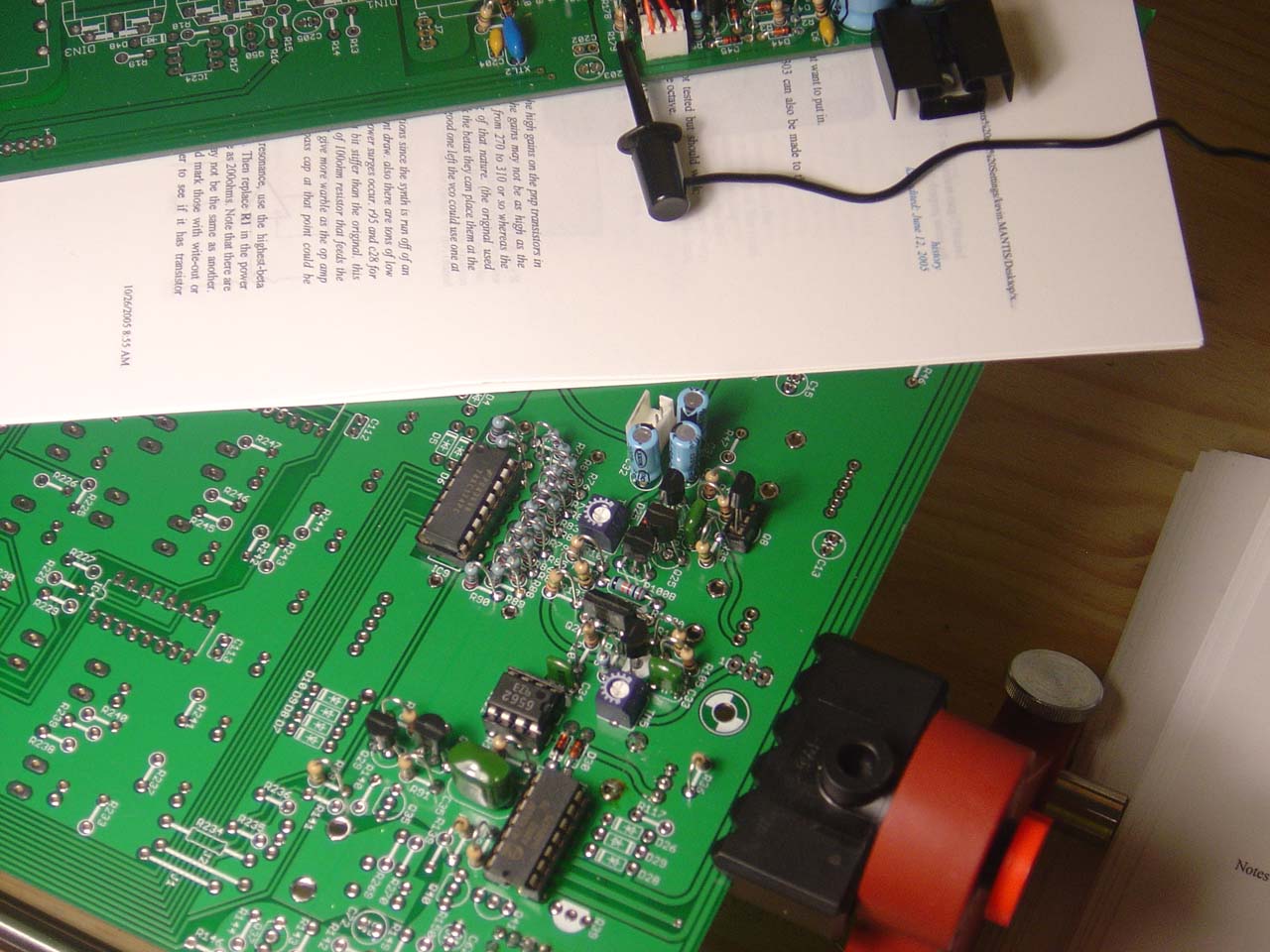
7pm-7:30pm Measured all the resistors and capacitors to verify they're good. All good... Wrote each value next to each component in case I want to select more accurate values for certain places in the circuit.
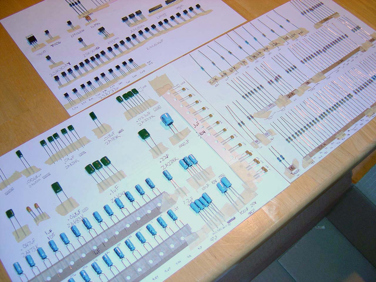
checking all resistor/capacitors. on the top page only the 733p transistors are checked.
Saturday 11.5.2005
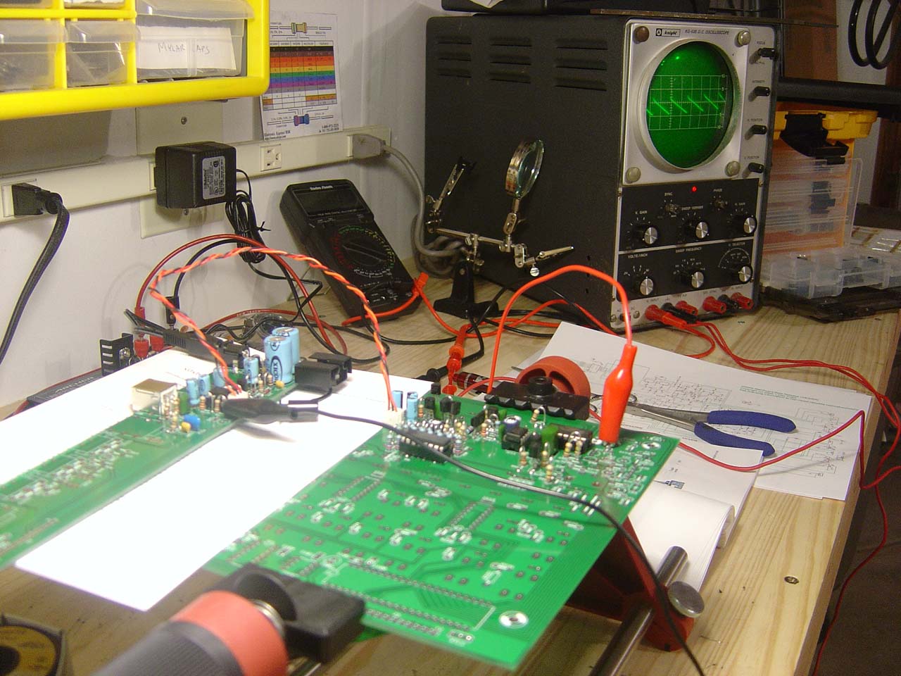
12pm-4pm Setup my workbench, cleaned it off and arranged all the stuff for this project. Built an lm317 based variable power supply (x0x manual says we'll need it for testing).
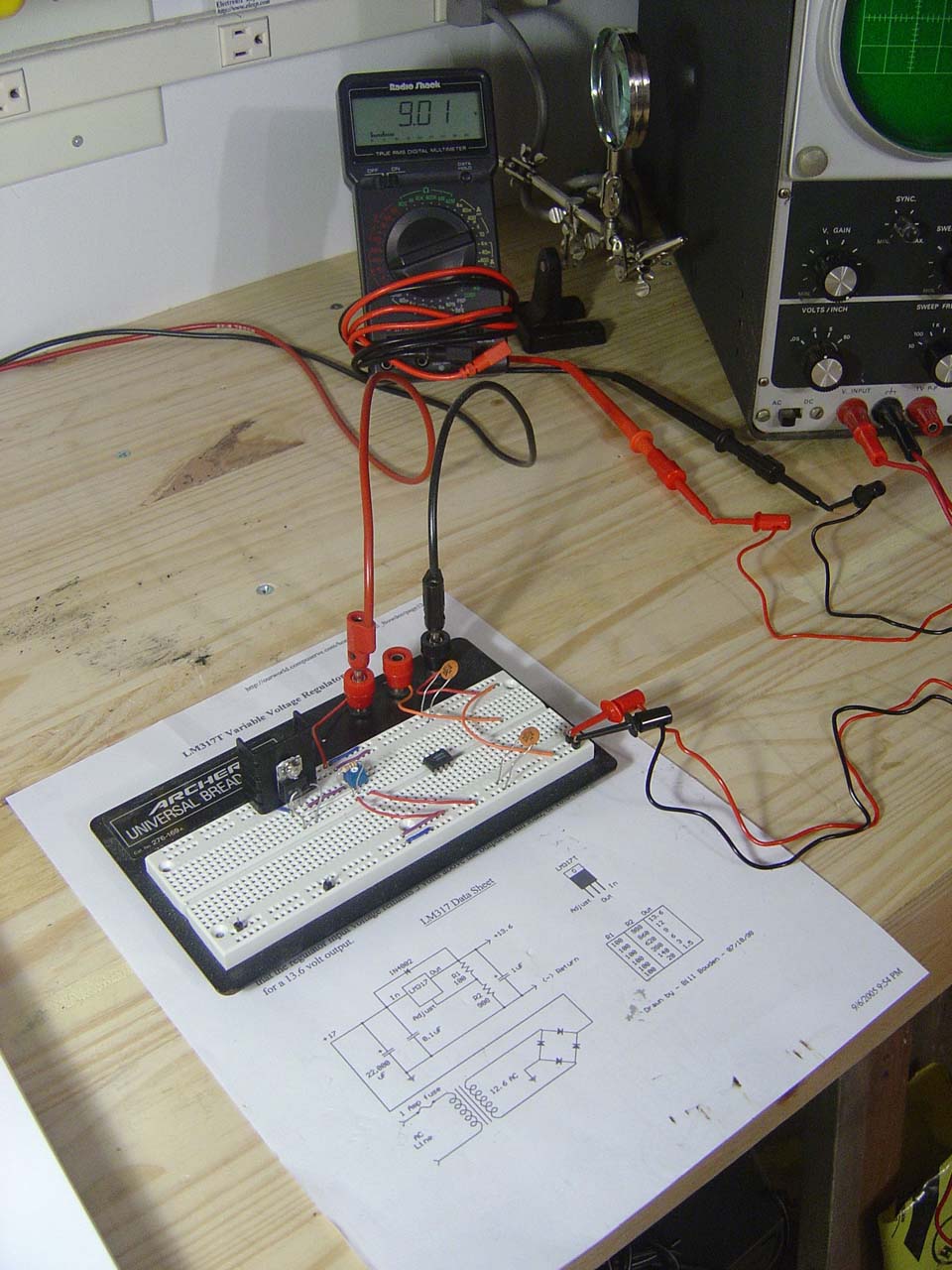
building the variable voltage regulator circuit (constant DC power supply is out of frame)
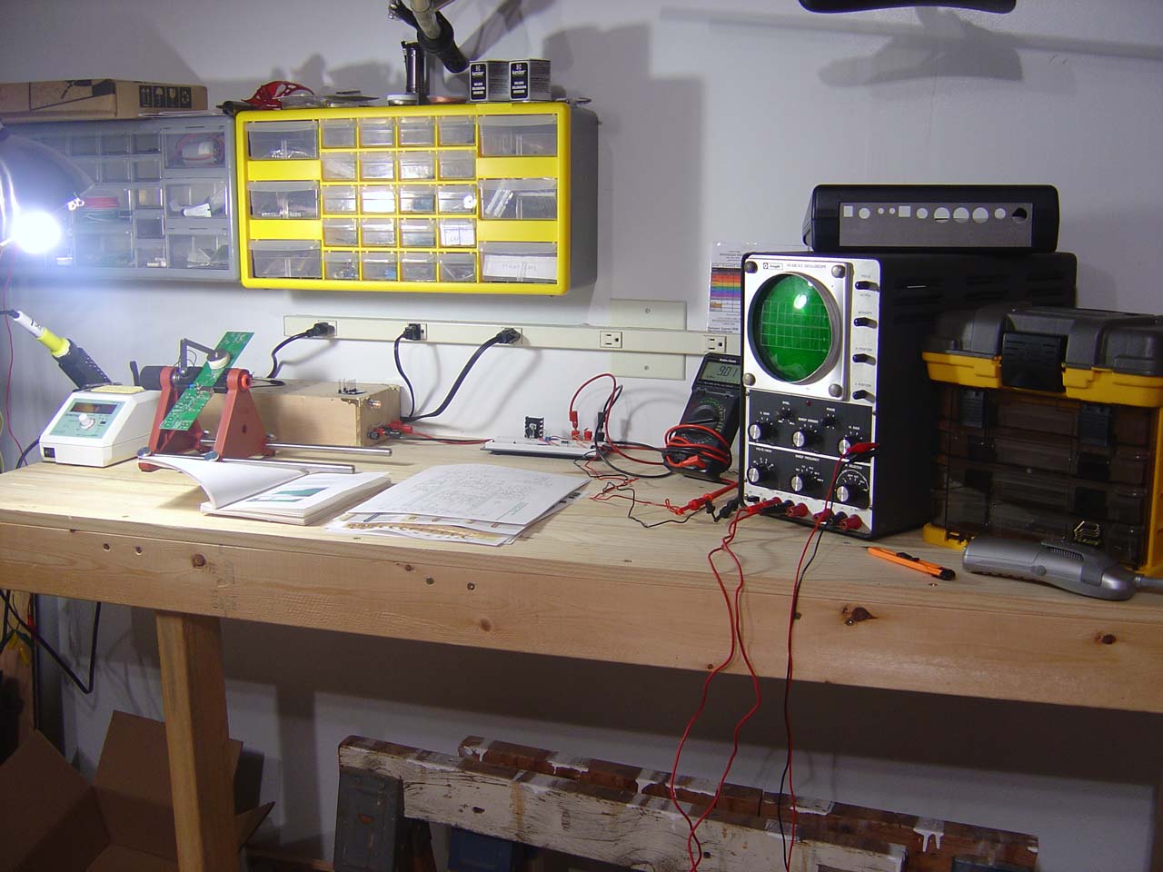
workspace ready to go
Sunday 11.6.2005
9:30am-12pm Started soldering the power supply unit. I socketed R1 so I could test different resistor values. The mod guide says that using a 200ohm resistor here instead of the 100ohm adds a little instability, making the power supply more loose like the original 303, having this socketed will let me try out different values.
1:00pm-3:45pm Finished up the power supply. All tests indicate success. Tuned the 5.33 voltage, and added a socket for the power jumper instead of the stock one that came in the kit.
finished power supply

here you can see the socketed R1 to the right of the big blue caps.
9pm-10:30pm Started soldering the VCO. I socketed q8 in case I get higher beta transistors. For the two 733p's in the VCO I used transistors with beta of 325.
Monday 11.7.2005
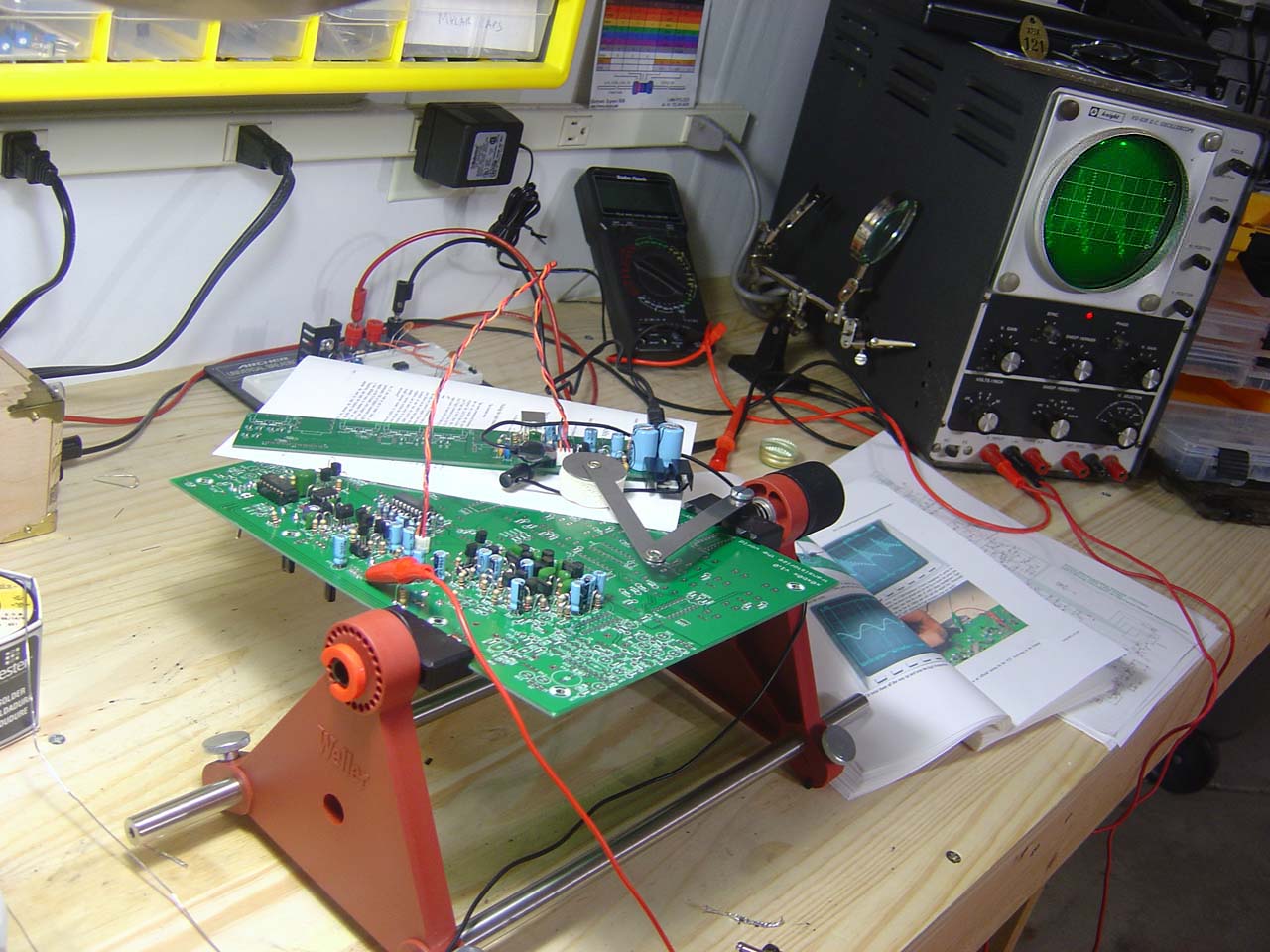
7:30am-9:30am Finished soldering the VCO. I ended up using the detented pot for tuning, I think it will be convenient while the synth is in tune. Maybe someday I'll mod the x0x to have a fine tuning adjustment stick out the back, until then tuning calibration is done inside on a trimpot. Testing of the VCO shows the correct DC offsets for saw and sqr waves.
First potential problem: The AC voltage seems low, only 1.58VAC for saw and 1.1VAC for sqr (expected 5VAC(saw) and 4VAC(sqr), per the fab manual). Using cheap headphones to probe the waveform switch I can hear that both the saw and sqr waves sound correct, and tuning knob does bend the pitch up and down. Waves also look correct in oscilloscope. So at least the VCO sounds correct. UPDATE 11/7/2005: the readings are low because my meter reads voltage in RMS! Not a problem.
Second potential problem: Am seeing some instability at times where the waveform jumps up an octave or so. Not sure why, but it seems to happen unpredictbly, only when I'm touching a lead to the waveform selector switch (the place you test the signal), or touching the switch (interface end) with my fingers. If I attach the lead and leave it all alone, it seems to stabilize to either the low or the high pitched waveform (doesn't seem to settle-to/prefer either one). UPDATE 11/7/2005: apparently the frequency floats around because the input to the VCO is not defined at this point, and because I didn't supply a voltage for testing purposes. Thanks to the x0xb0x forums for this one... I didn't apply the test 2VDC and 3VDC CVs because I was going to wait until the x0x was completely built to test the tuning using the keyboard buttons. So... Not a problem.
So the question at this point is: are these real problems, or just the product of testing. Is it something that will stabilize when I'm not poking around the circuit? UPDATE 11/7/2005: All is good, VCO checks out, no problems, see above updates...
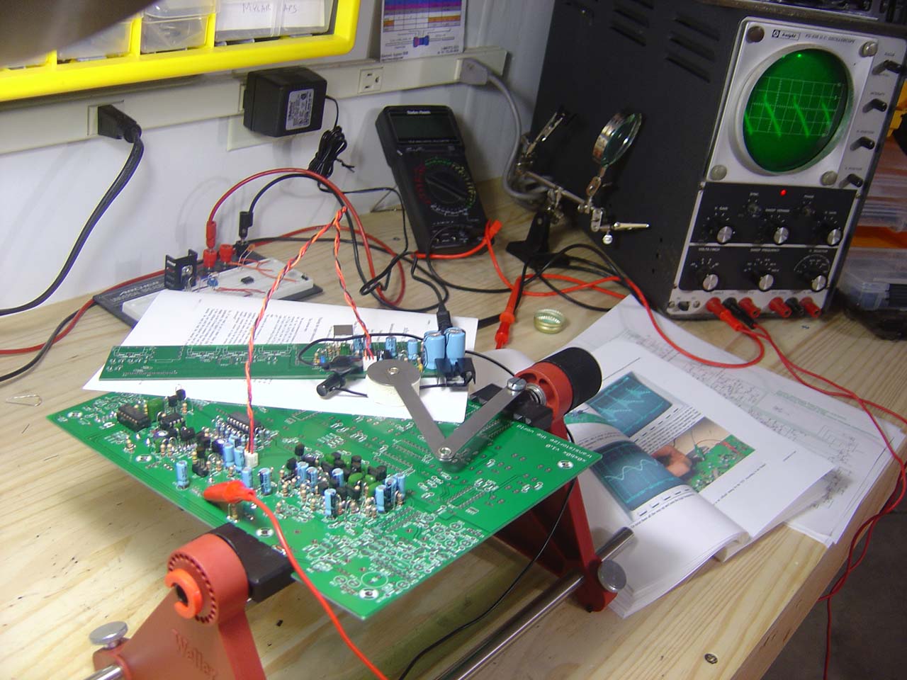
We have a square wave!
See how it tapers slightly at the top of the square, this is expected.
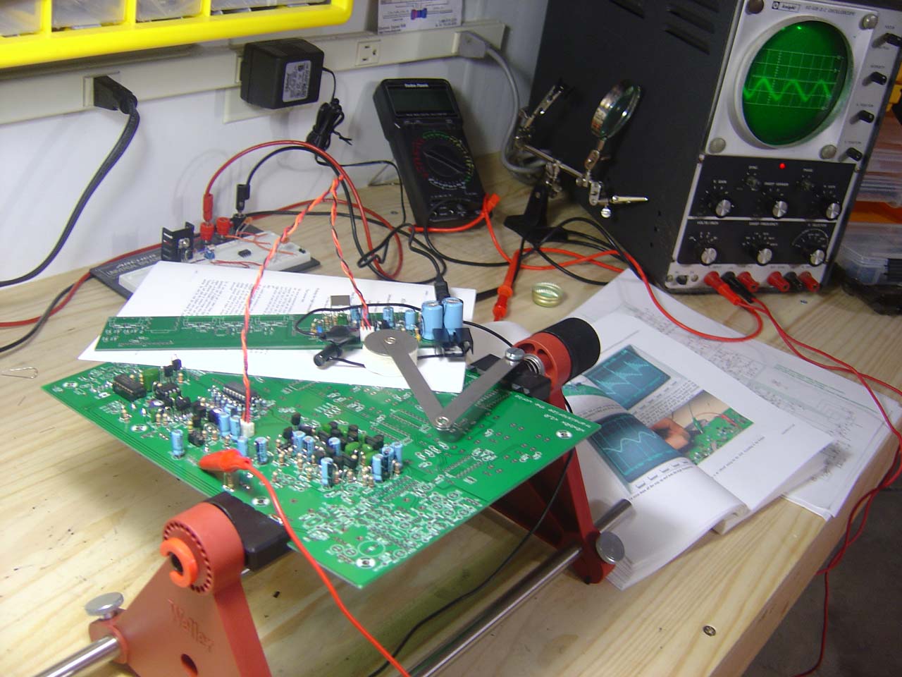
We have a saw wave!
Closeup of the completed VCO section, here you can clearly see the socketed Q8 (733p) transistor, and the socket for the J4 power jumper from the IO board
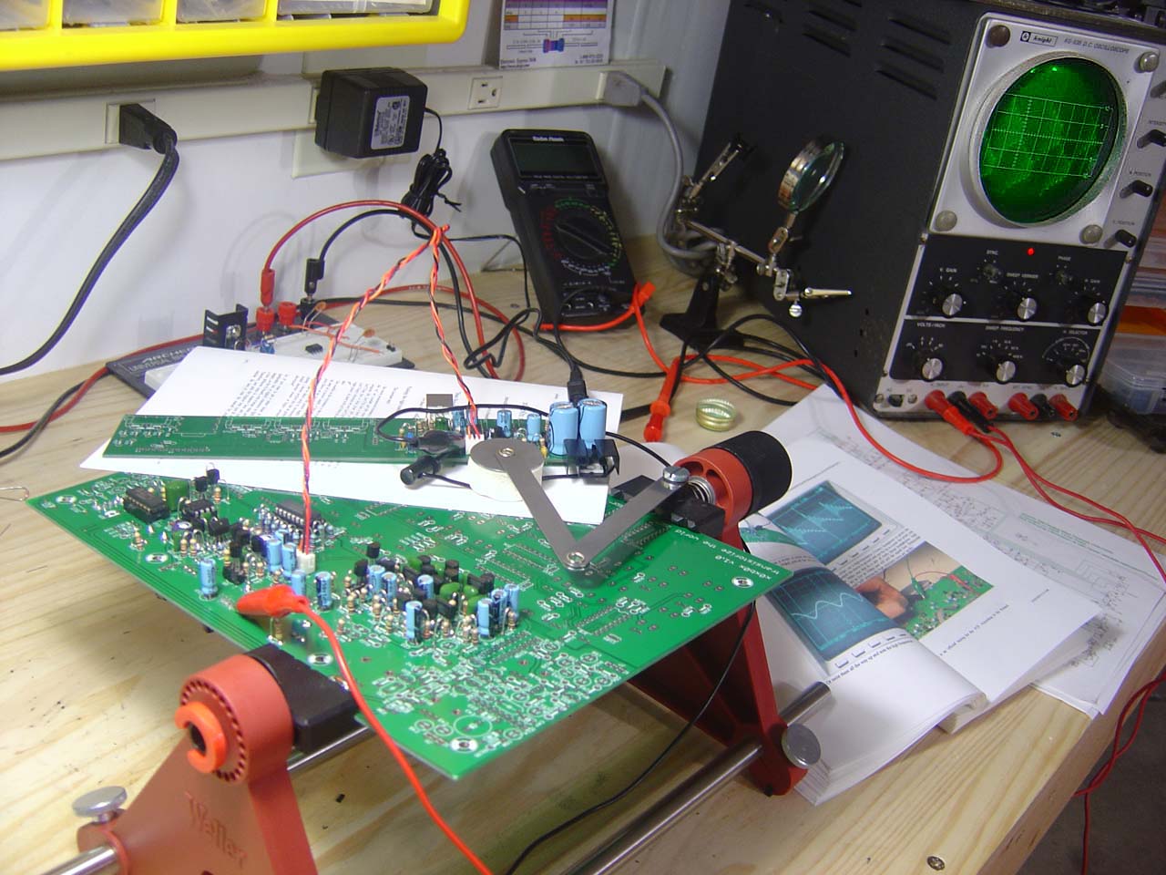
The completed VCO section during testing
Tuesday 11.8.2005
9:00pm-10:00pm Started the VCF section, soldered in all the resistors.
Wednesday 11.9.2005
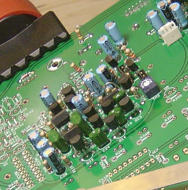
7:30am-9:30am Finished soldering the VCF section. I used sockets on the SA733p transistors in q9 and q10 (see picture), and inserted 733's with the highest beta I could find, 350 for q10 and 335 for q9. Using the high beta was described in the mods documentation as making the x0xb0x sound closer to an original 303.
Testing using cheap headphones to probe the cutoff and resonance pins: Cutoff works, resonance does not. Realized I put the 1M pot in place of the 50K pot, will need to remove, probably with solder sucker and solder wick. More on this tonight...
The completed VCF section
7:40pm-8:20pm, 9:55pm-10:45pm Unsoldered the incorrect 1M pot and replaced it with the correct 50K pot. The transplant went smoothly without damage. Resonance and cutoff are adjustable now by twisting the knobs. VCF section is now complete and tested!
Testing saw wave at cutoff and resonance set to full.
On the scope: notice the harmonics within each period of the saw wave.
Testing the saw wave with resonance turned down, looks just like a normal saw wave
Testing saw wave with cutoff turned down, look like a sine wave.
Here's the sqr wave at full cutoff and resonance
On the scope: notice the extra harmonics within each period of the sqr wave.
Thursday 11.10.2005
8:00am-9:30am Finished the Envelope section. Tests indicate success. I see a pulse signal at the output when I apply a trigger voltage to the Envelope circuit. This was a pretty small section to do so went pretty fast. Also, this is where that 1M pot belongs (see vcf section above).
Finished Envelope Section (upper right corner)
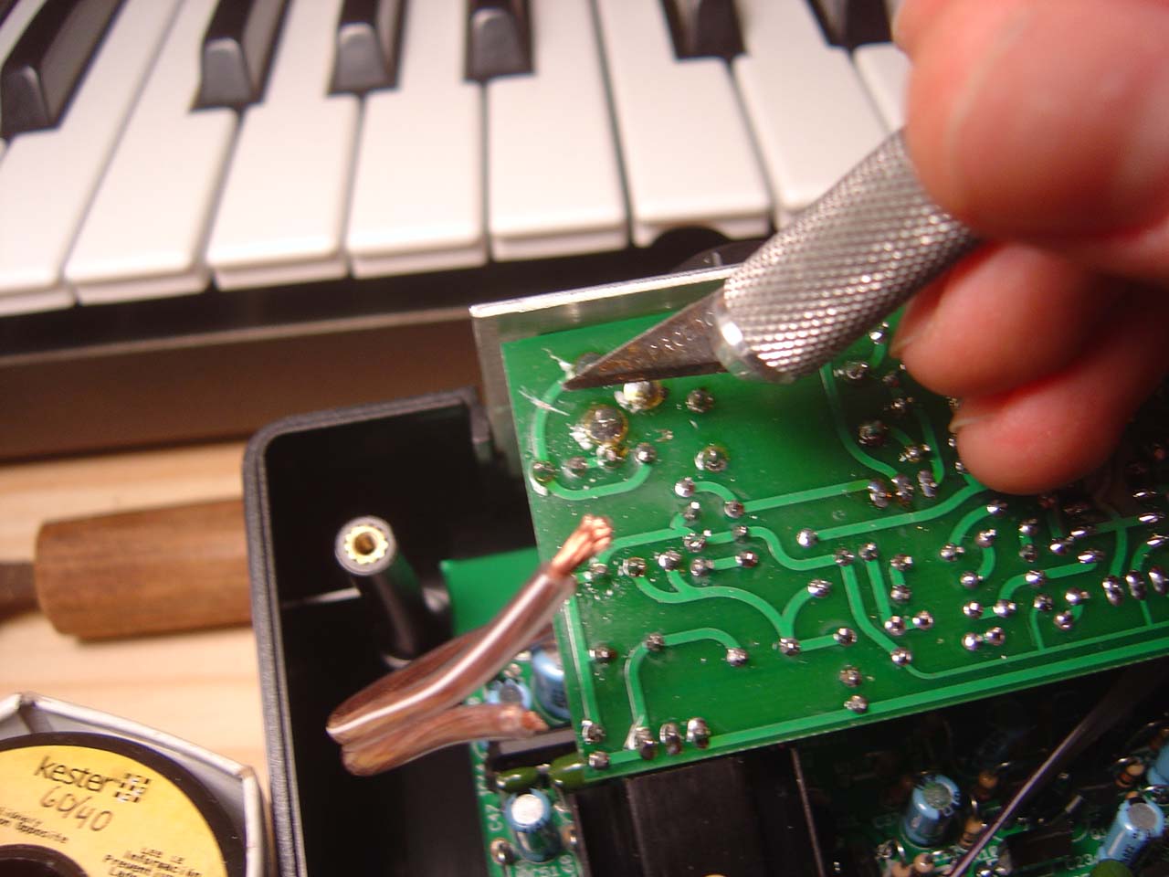
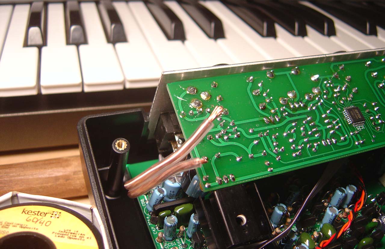
8:30-10pm Started work on the vca section. The vca has an optional configuartion (to use the BA662 chip instead of the BA6110+transistors) as well as a fragile chip (the BA6110 vca chip), so I decided to use sockets for both protection and future reconfiguring. Cut DIP sockets apart into homemade SIP sockets using exacto knife to create sockets for the 4 transistors, Q1,Q2,Q3,Q4, and created 2 9pin sockets for each SIP chip. I chose 2 of the higher beta 733p transistors for Q1 and Q2, 325hfe each. I then soldered in the remaining transistors, and stuck the rest in their respective sockets.
![]()
UPDATE 7.2.2006: I acquired 2 of the original Roland BA662A chips from Technology Transplant (user chipforbrains on eBay) and
tested them against the BA6110 chip.
In short, there's no difference other than the BA662A is a little more quiet.
Click here
to read an in-depth report about how the original Roland BA662A vca chip compares to the x0xb0x BA6110 vca chip. My two BA662A chip numbers are #209, and #504.
Friday 11.11.2005
8:00am-9:30am Soldered in the rest of the vca. Testing using my headphones on the pin of the VR8 voltage knob, I got no sound. Spent some time looking for bad solder joints, bridges, etc. Took measurements of all the transistors and the 6110 chip. posted results on the forums. Lots of other people on the forums with the same results. Looks like a batch of bad chips were sent out, confirmed by a posting from ladyada - she's sending out new chips for us. Project's on hold until then.
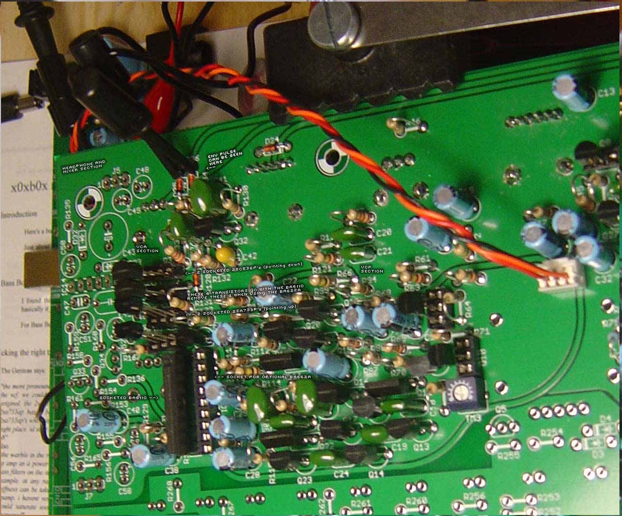
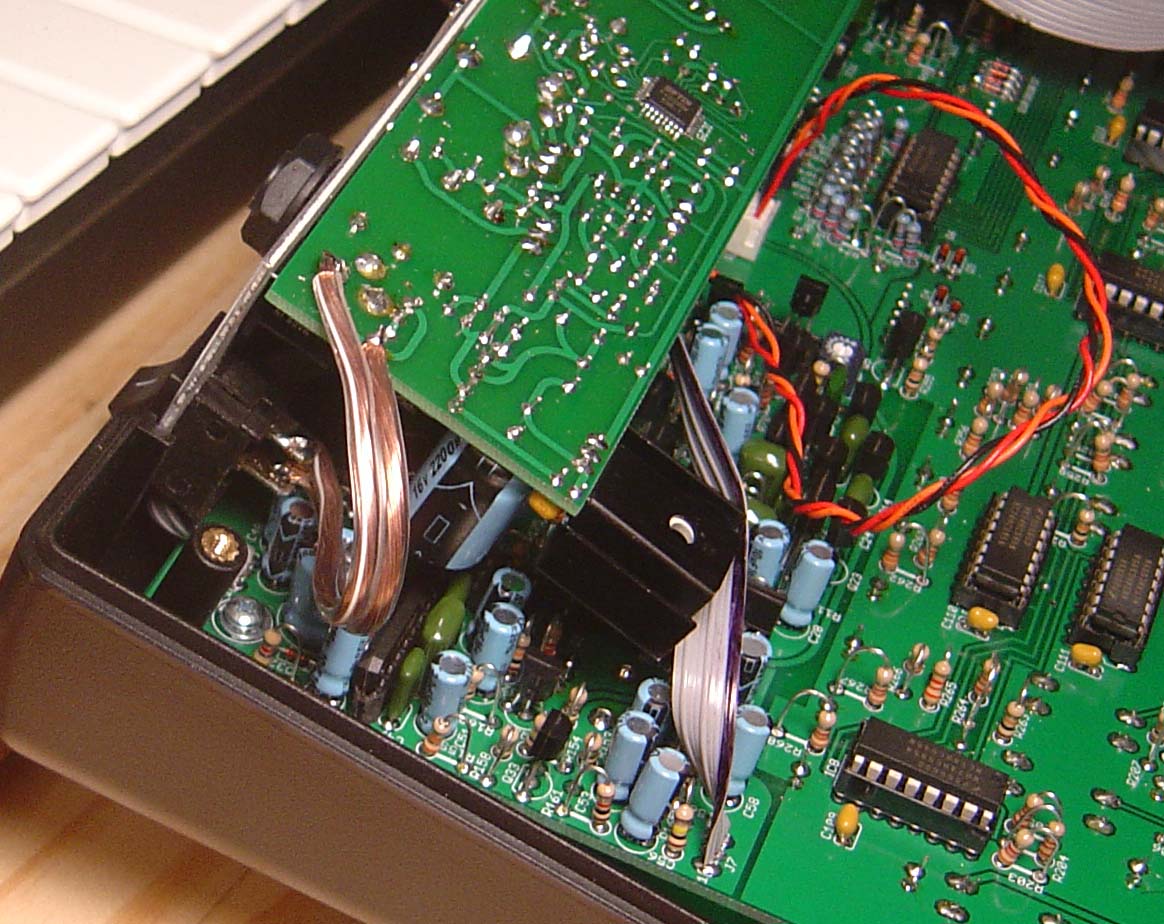
Finished VCA Section, socketed for future upgrade to the (rare) BA662 VCA chip.
Click image to see annotations
Tuesday 11.15.2005
8-10am Worked on a custom LED colorscheme, came up with purple/orange/blue, which are sort of my regular colors. Browsed eBay and found parts to order. Ordering from hong kong is strangely both expensive and cheap at the same time. Cheap LEDs, with expensive shipping. But overall I saved a bunch of money over ordering LEDs from US locations.
Final LED design (fake "photoshopped" image)
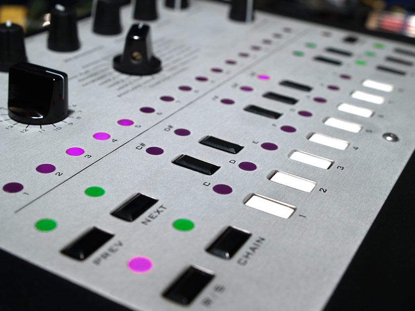
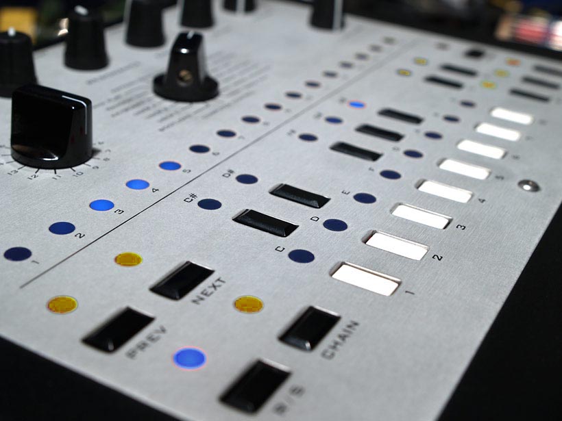
Some other LED designs, while good, didn't make the cut...
UPDATE: I ended up with the blue/orange/white design (on the right) in the finished synth.
10am-3:30pm Went ahead and soldered the headphone and mixer section. Afterwards I finished the IO board including all the in and out jacks. At this point the USB is ready to test. Plugged in the power and the USB cable into the computer, and it's recognized, asking me if I want to install a USB serial device... So I install the driver for it. So far so good. I move on to start the digital section where I soldered in all the DIP sockets for the ICs...

Finished Headphone/Mixer Section
6-11pm Went to visit ceedub, another local x0xb0x builder. dj_statikfire also met up with us to help debug some x0x issues. Looks like ceedub's digital section is dead, it may be the clock generator. Hung out, played with some vintage synths, and discussed future projects including the 9090 drumsynth and the MIDIbox SID, a synth based on the Commodore 64 sound engine.
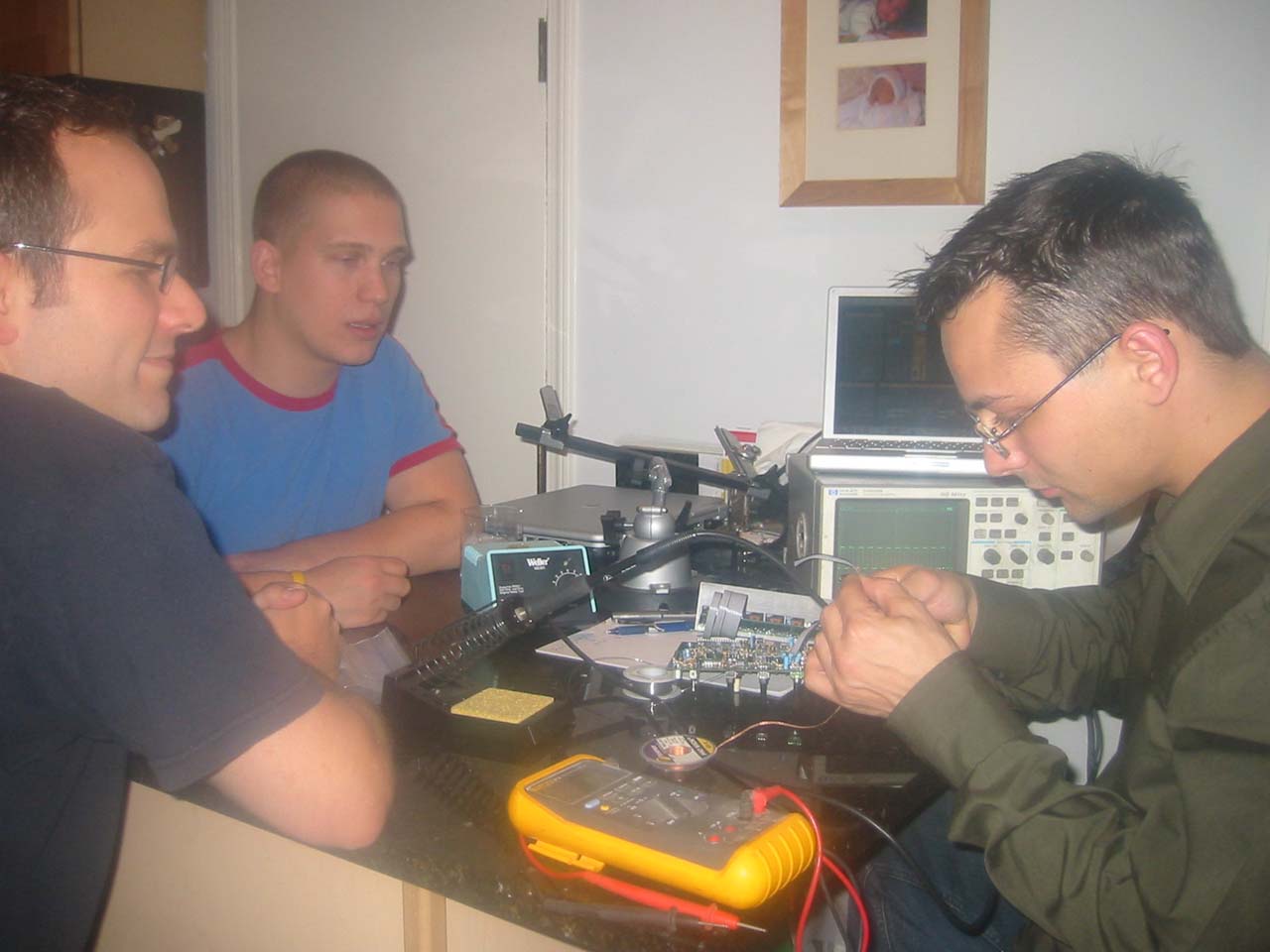
local chicago gathering of x0x minds. statikfire's troubleshooting an issue with ceedub's box.
Wednesday 11.16.2005
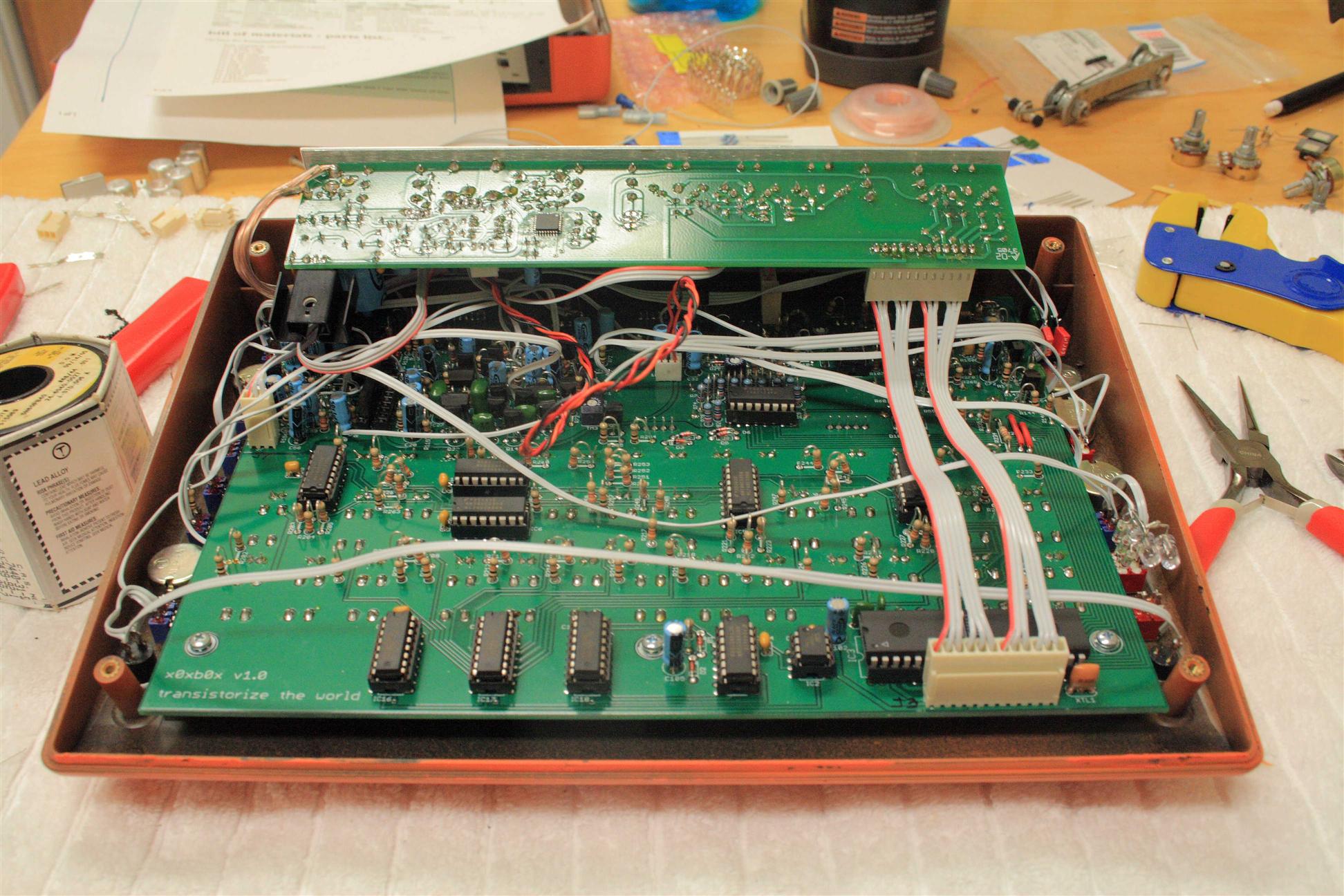
10-5pm Finished the digital section, but left out the LEDs and the resistors for the LEDs. I'm waiting for the custom LEDs to ship... I went ahead and jumpered the boards together. Also, got 5 replacement ba6110's today from MCM, unfortunately none of those work either, they all came from the same batch as the chip that came with the x0x. I will have to wait for the replacement from adafruit, hopefully it works. I did get to listen to the synth a little by probing the VCF section using headphones on one of the Resonance pot pins. Looks like the digital section works: putting the synth into "random mode" outputs random notes/velocities. If I twist the tempo encoder knob, the speed of the random notes changes. In "keyboard mode", hitting keys changes both the pitch of te notes (in the VCO) and the attack of the notes (in the VCF). Octave up/down buttons works as well, changing the pitch of the keyboard buttons over the entire 4 octave range. I will need LEDs to test out some of the step programming features (I think), and will wait until the circuit board guts are installed into the final box before I plug into my computer for firmware update and to test out MIDI and USB communication with the Atmel processor... For now: Project's on hold until I get the custom LEDs and the replacement VCA chip (BA6110).

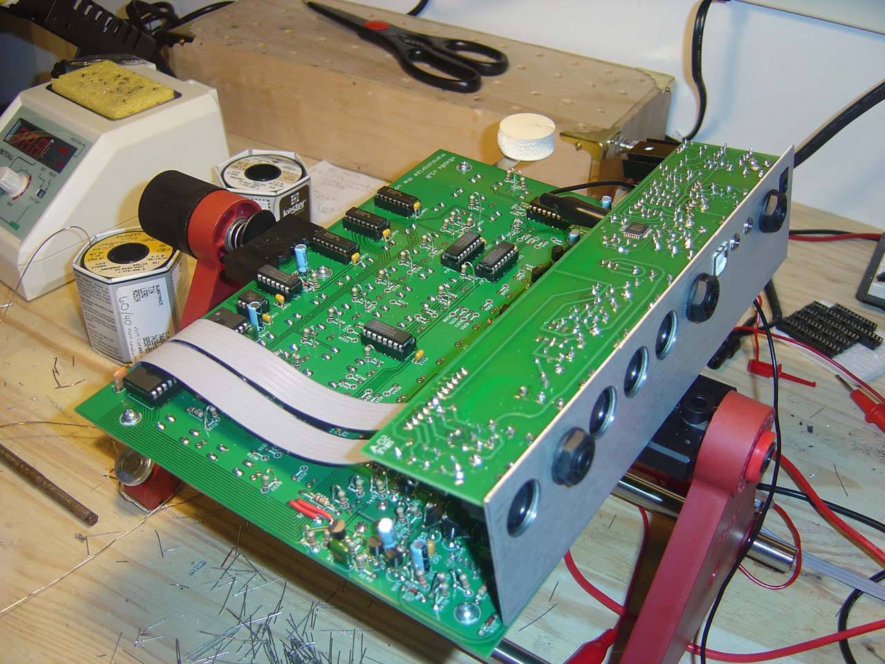
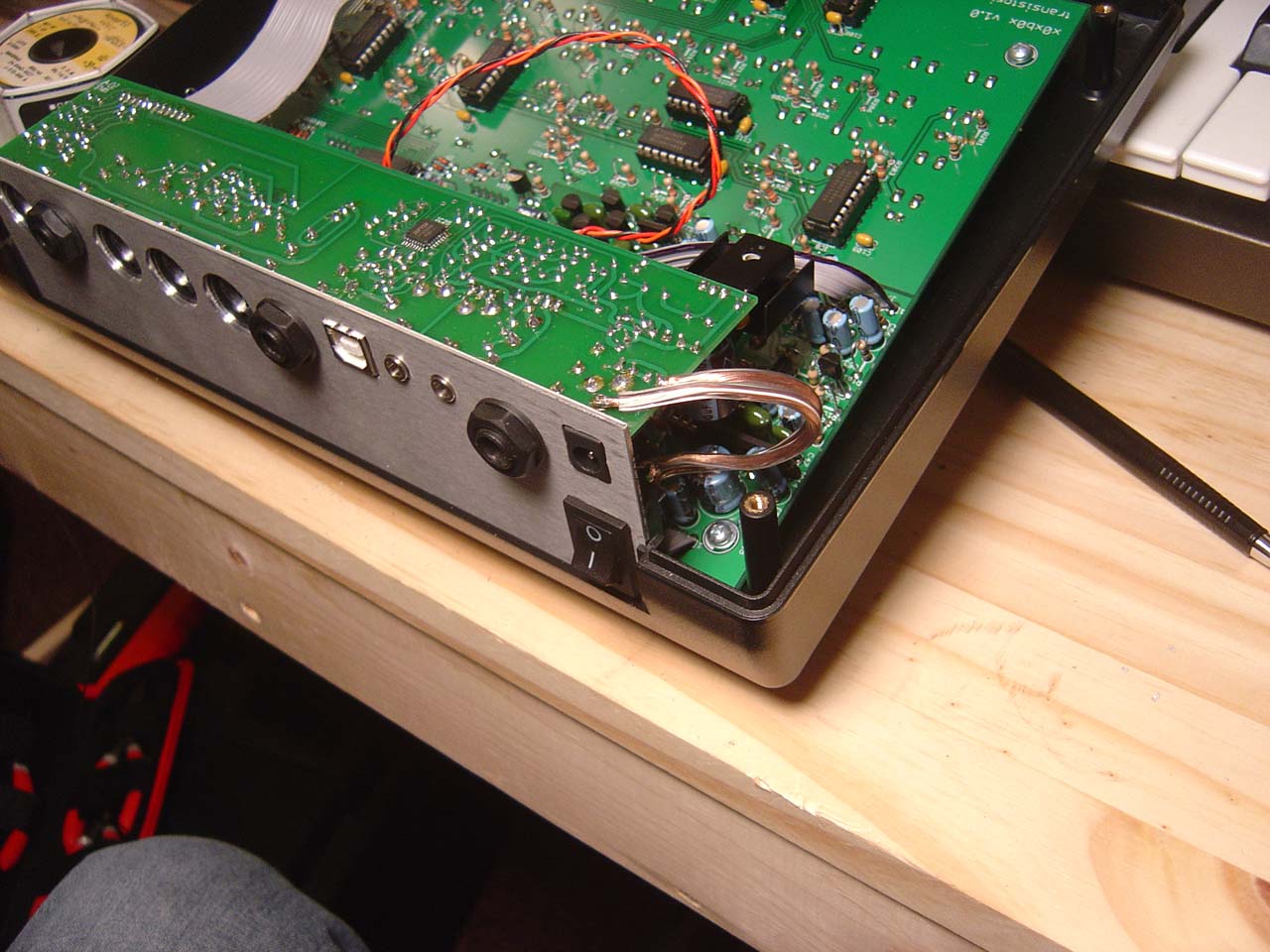
Almost done, completed x0xb0x sans LEDs and with a broken BA6110
Sunday 12.06.2005
5pm Realized I hadn't checked the mail since friday and it figures, because both the BA6110 chip replacement AND the new LEDs were in there. I stuck in the new 6110 and it fixes the problem - the x0x now makes sound out the headphone jack! It was pretty fun playing with the knobs and pressing notes...
Also plugged in some LEDs to test the colors and brightnesses (trying different resistor values). I screwed up and only ordered 20 pink (and 20 more 3mm - wrong size!), not enough 5mm's. That's ok though, because the pink LEDs are more magenta than purple. Color scheme I'm thinking now is blue/orange, with white tempo light. We'll see. LEDs is all that's left and then I can put it all in the box.
Thursday 12.08.2005
7:15am-9:30am Counted out LEDs, 8 orange, 1 white, and 31 blue. Ground down all 40 of the LEDs to have a flat diffuse/opaque top on them instead of the blinding focus-dome LEDs usually have. To make them all the same, I just eyeballed them. Nothing scientific or flawless. I call this the organic approach, no two LEDs are the same, they're like snowflakes. I usually stopped grinding when the dome seemed completely ground off (with just straight cylendar sides left, and maybe an oh so slight curve into the top).
Here I take normal transparent domed LEDs and grind the tops down so
that they are flattened and diffuse looking. After grinding, the
LEDs are tested with resistors before soldering into the synth.
Soldered in all LEDs and all resistors. Powered on and nothing looks wrong switching into a couple different modes. Will test thouroughly later. The white LED is kind of neat sitting there blinking on the tempo.
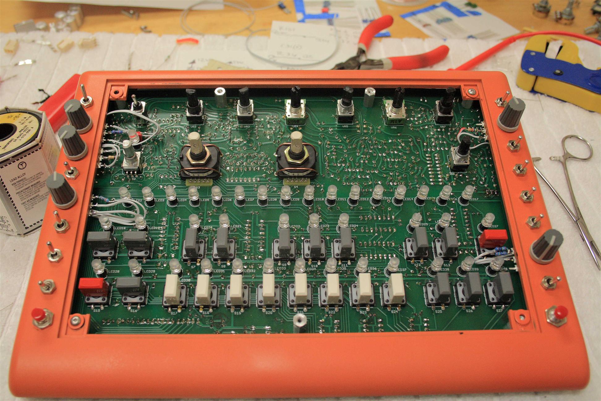
LEDs are in, but they're kind of crooked. This makes fitting the top panel
very difficult! The top panel doesn't go on until these are all
straightened perfectly.
8pm-12am Went over the LEDs again to ensure tight fit against the PCB, spent a while bending the LEDs so the front panel would fit over them. Since they're flat, it's really hard to get the panel down over them. Put it all together in the case and knobs.
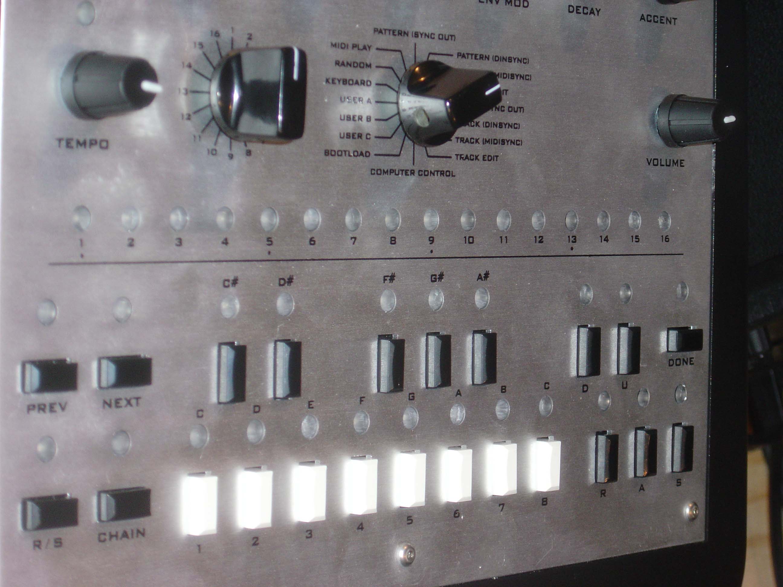
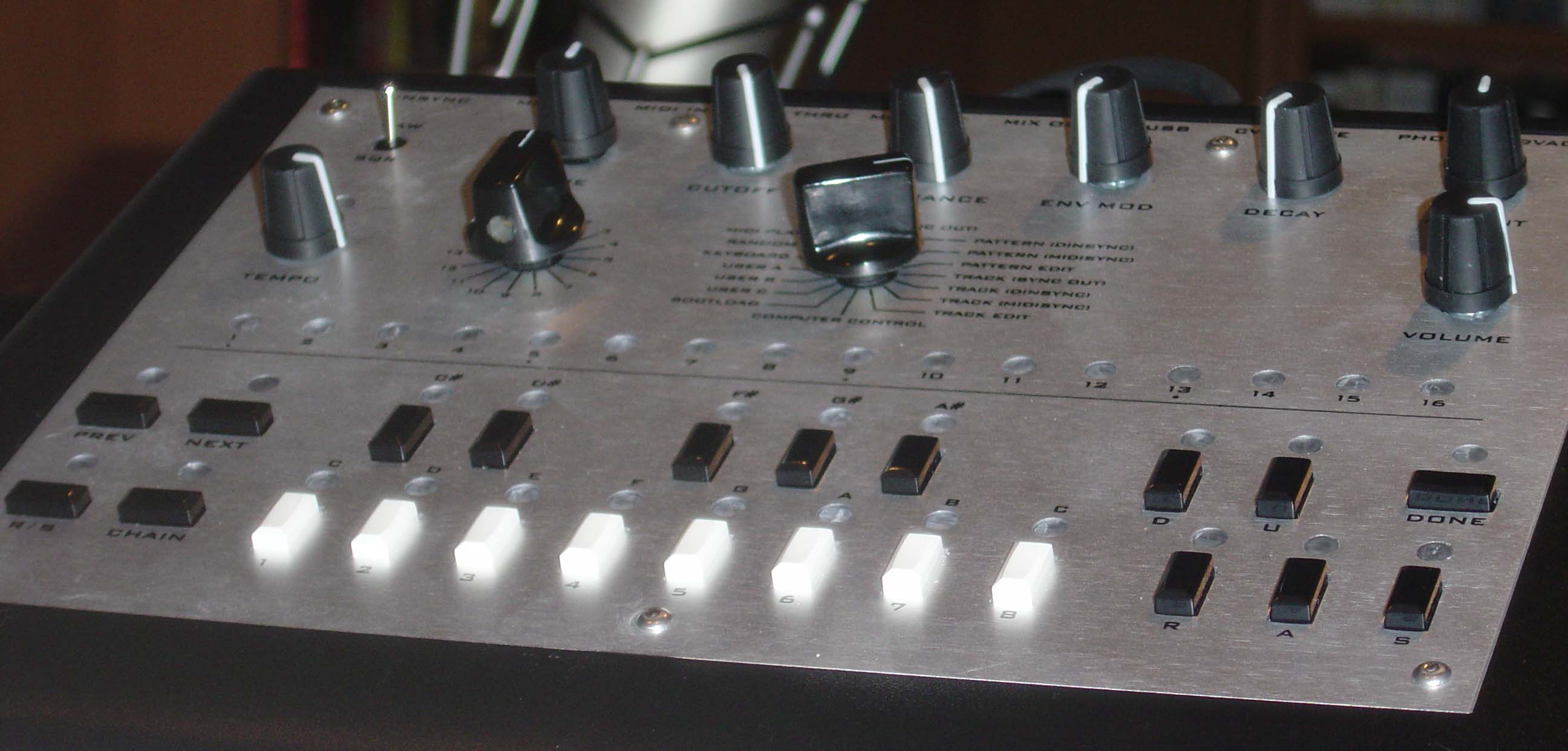
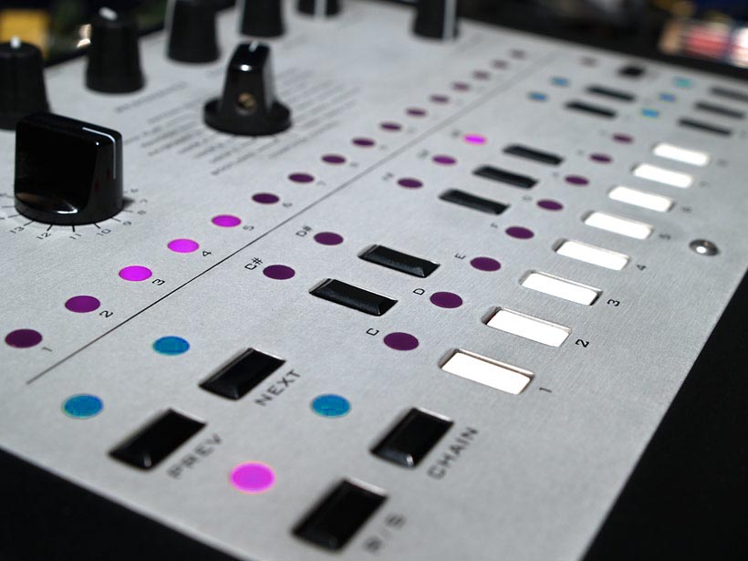
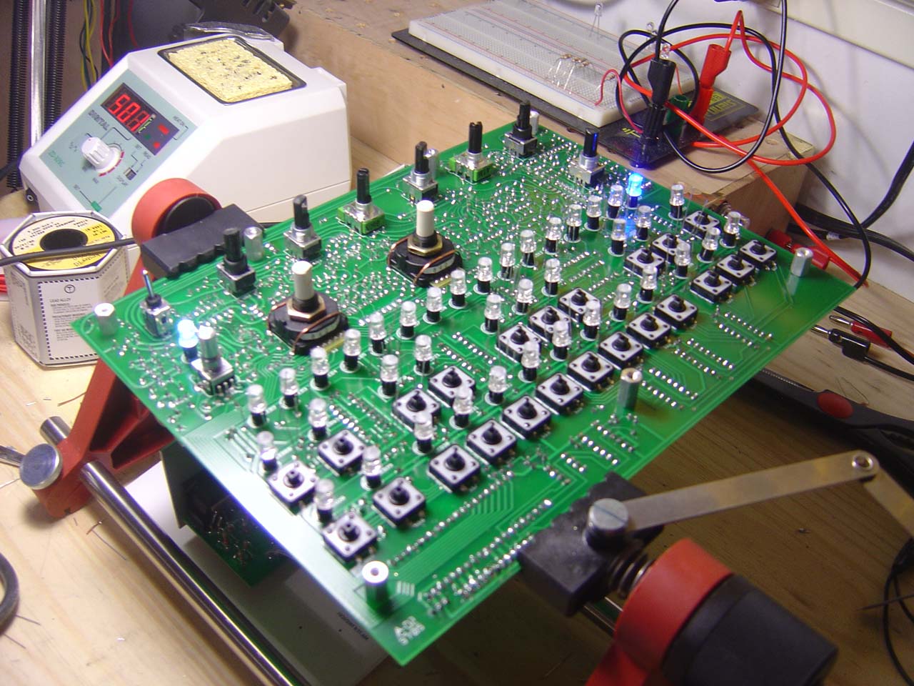
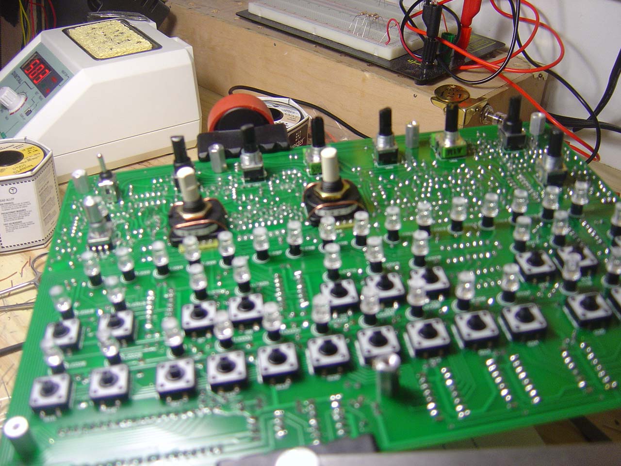
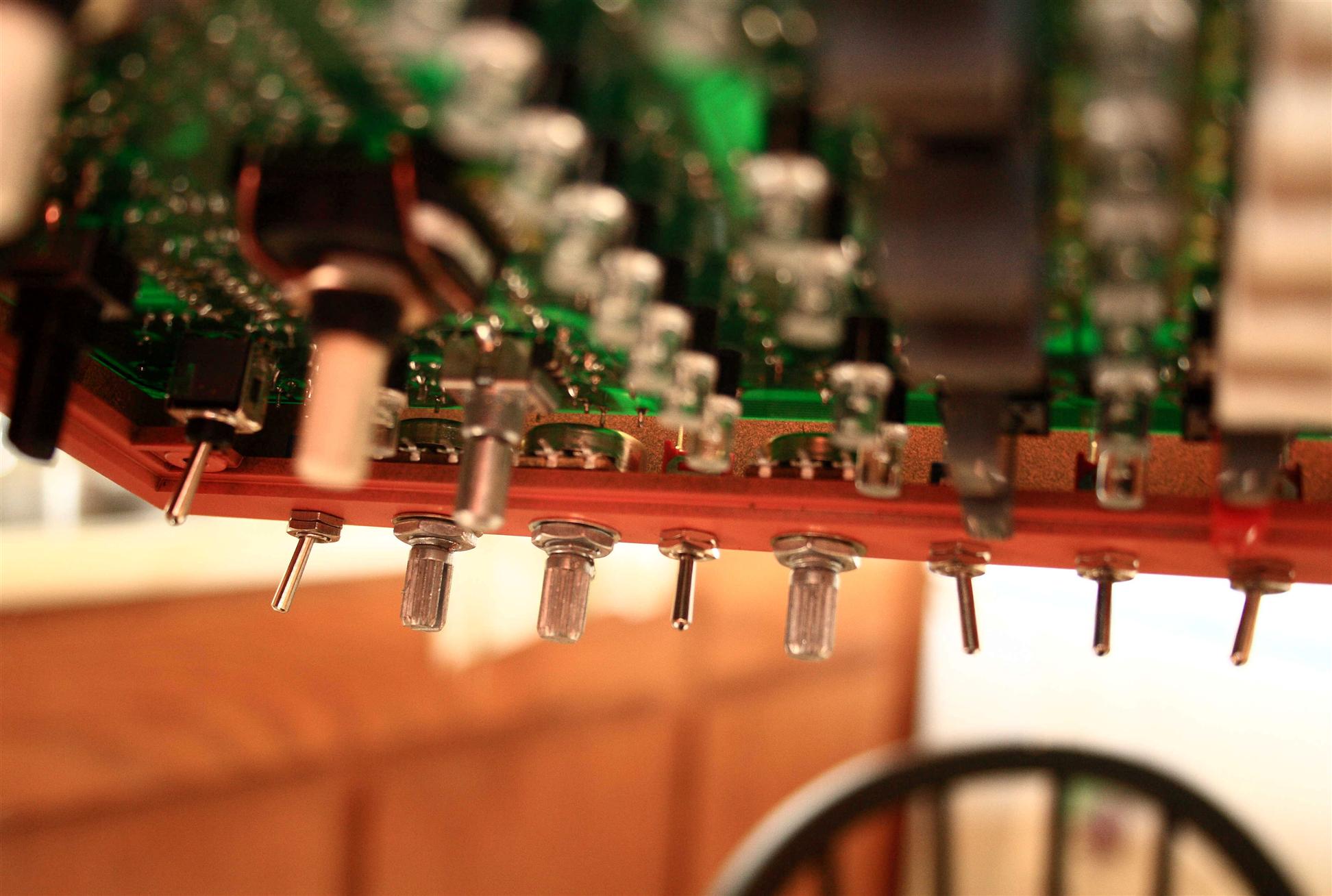
Closeups of control surface with the new custom flat/diffuse LEDs
Spent some time playing with the x0x connected to a Line6 POD, some really neat sounds coming from it, its simplicity of sequencer programming and the neat bubbly noises are making this a lot of fun and really worth it. However, I'm noticing that I will definately need to tune the synth, the octave notes C0, C1, C2, and C3 are all very out of tune from each other...
The LEDs are also a little (well, ok, a lot) bright. I apparently have poor perception of what passes as an indicator light (remember I even tested them?). I really should have done a side by side with my other gear to compare... :( Planning on higher resistor values tommorow.
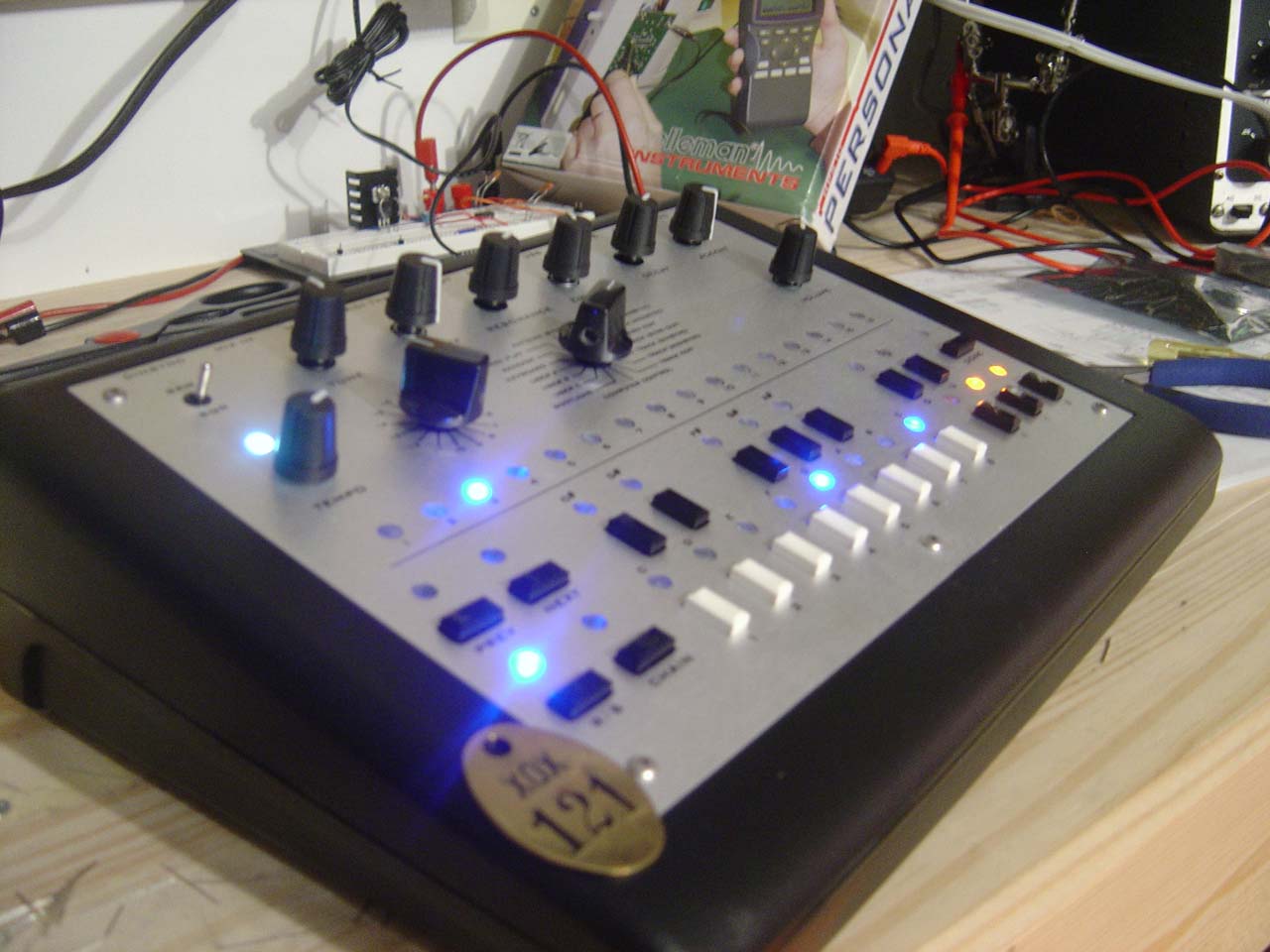
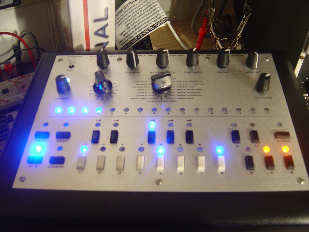
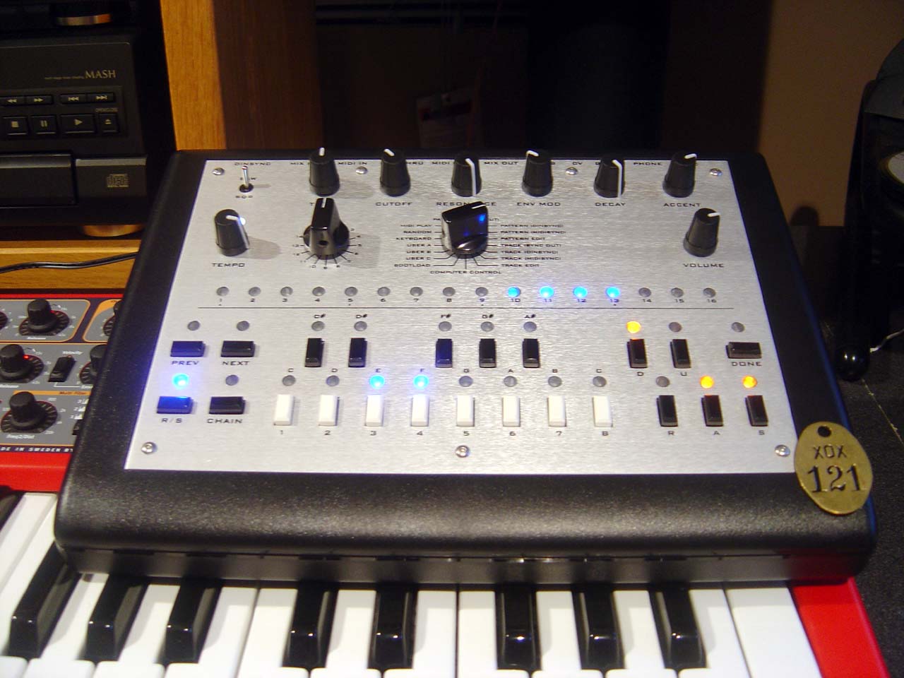
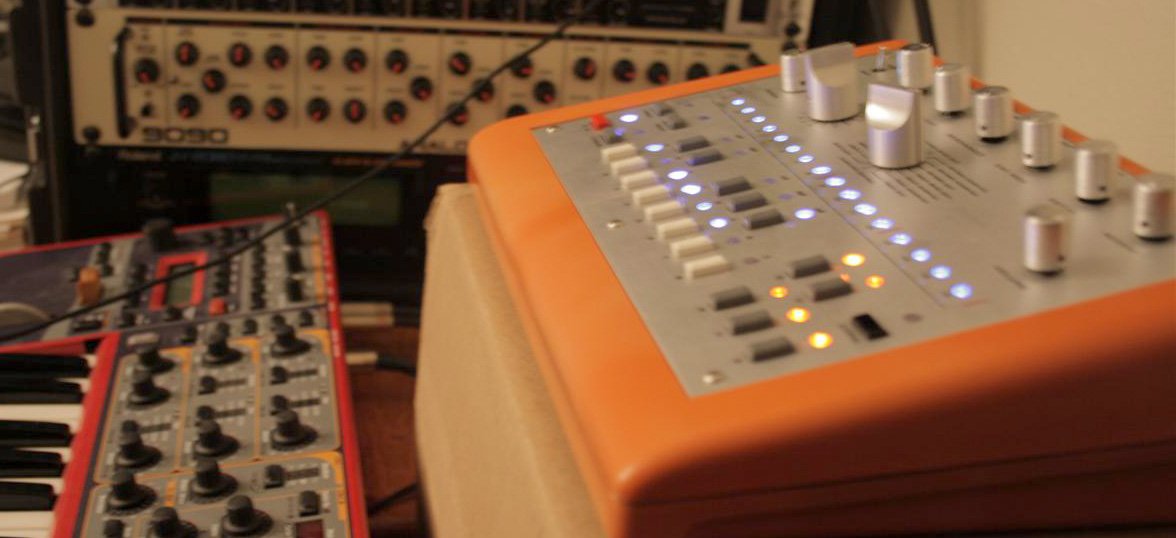
x0xb0x #121 operational! (ouch, too bright!).
Saturday 12.10.2005
4pm-6:30pm Wired in new 3.3k resistors for the blue LEDs, it's worlds better, still a touch bright, but still in a good range for indicator lights (no more wincing!) blue is very usable now. But the orange is a bit too bright. I'll put in some 2.2k's for the orange LEDs tommorow.
More playing with the x0x tonight and spent some time showing a friend what the "303 sound" is all about. He "got it" right away, so even untuned, the synth speaks for itself. Fun! :)
Sunday 12.11.2005
8-11am Wired in 2.2k resistors for the orange and the white LEDs. This makes the x0x very normal (less wincing!) to look at...
I also spent some time tuning the synth (this is where we set all the trim pots hidden inside on the circuit board). The power supply was still giving 5.33V (good), so I moved on. I then hooked up the scope to a pin on the resonance pot and proceded to tune up the x0x's VCO (for pitch) and VCF (for resonance pitch). To tune these, there are 3 pots: 1 for pitch-scaling that affects notes octave to octave (it's a voltage scalar), 1 trimpot for pitch offset, and 1 for resonance pitch offset. I set them in that order, and it was a breeze using the scope.
Here are some thoughts I was having about different tuning methods (feel free to skip ahead). I think a guitar tuner would have been more difficult to set the first trim pot, since usually tuners do not measure frequency rather just notes and sharpness or flatness... So doing with a guitar tuner I can see getting caught in a lengthy cycle of tuning the 2nd pot to get a good reading on the tuner, then tuning the 1st to see how the pitches work out octave to octave... Alternatively, If you have a good ear, it would be easier skip the equipment, tuning the 1st pot while listening to C1 and C2 notes being hit... then move on, not as precise as using the scope though.
I also added a bit of bicycle chain grease to the pot posts so that next time I have to open this up, the knobs won't be so stuck.
So at this point, x0xb0x #121 is done according to spec, plus 3 mods, custom LEDs, all 733p transistors chosen for high beta (to emulate the original 733pa in the tb303), and a 220ohm resistor in the power supply to "loosen it" to be more like the original tb303's psu. Future mods I'd like to do is a power switch, move the resonance tuning trimpot to be accesable external (pot or thumbwheel), etc... For now, I think I'll use the synth for a while. Here's the final pics:
x0xb0x #121, finished
.:: the end ::.
Mods
Friday 7.7.2006
8:30-11am Tonight I modded the x0xb0x to have an on/off switch on the back. So I finally tired of plugging and unplugging my power cord from the back of the x0xb0x to turn it on and off. As you may know, the x0xb0x kit does not come with a power switch or a means for mounting one. You are meant to plug and unplug the power cord (or use a power strip) to turn the unit on or off. So now, with this mod, I can switch on the x0xb0x without messing with the power cord! I think I got the switch from here, in case you're interested.
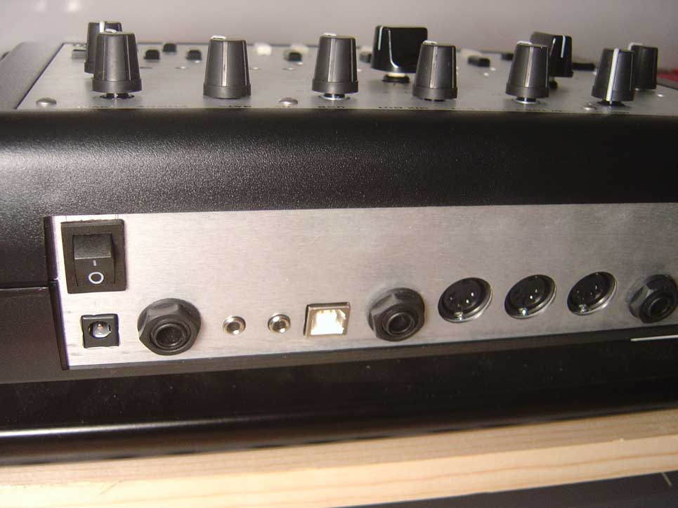
x0xb0x power switch mod
As you can see, I had to cut a hole in the aluminum. This is where a nibbler comes in handy. Our local radio shack was going out of business and I got a pair for cheap. It's very special purpose, but without them cutting aluminum would be a giant pain in the ass.
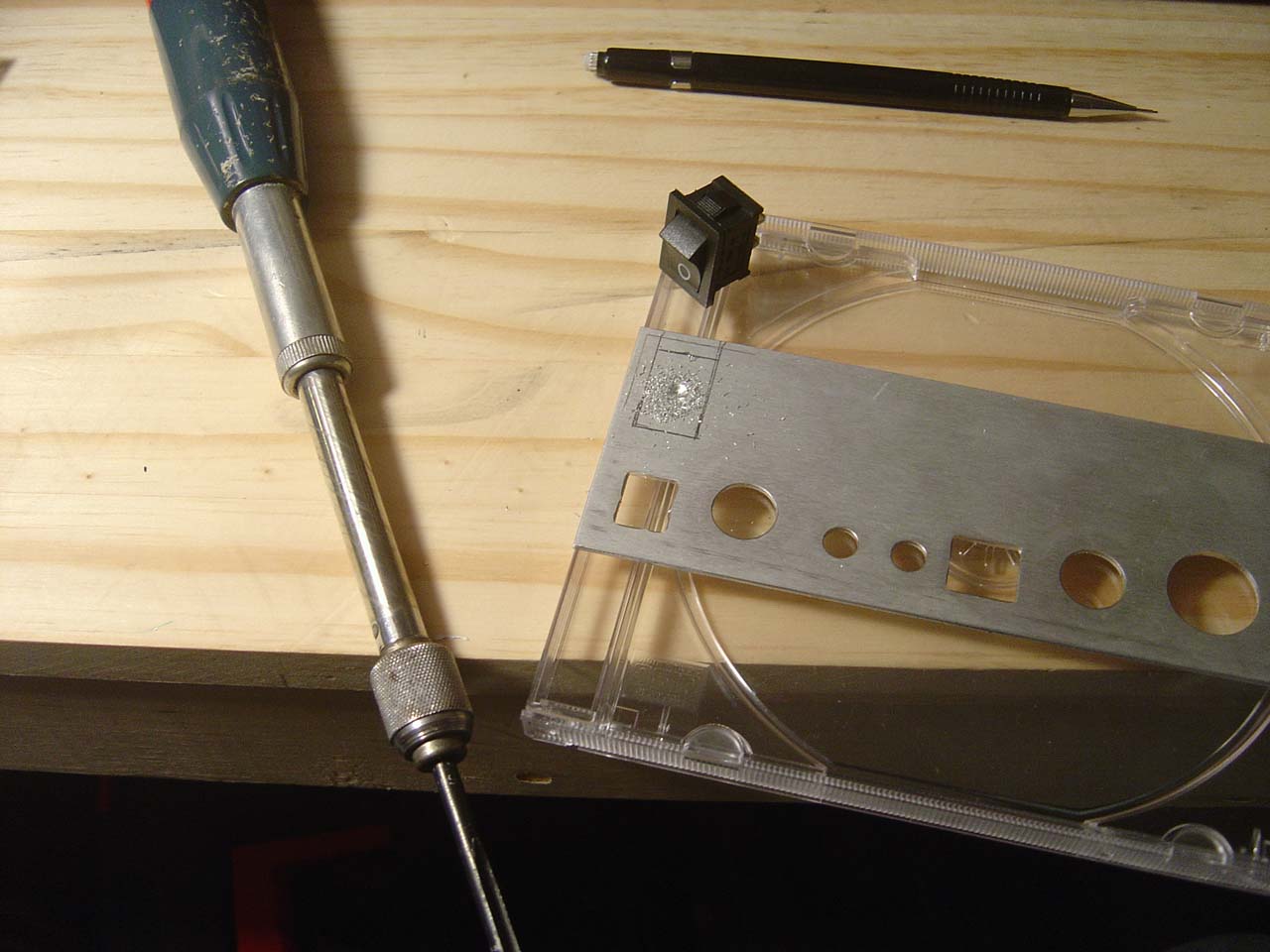

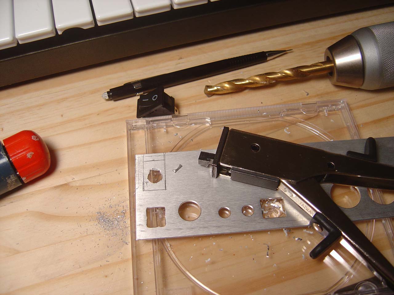
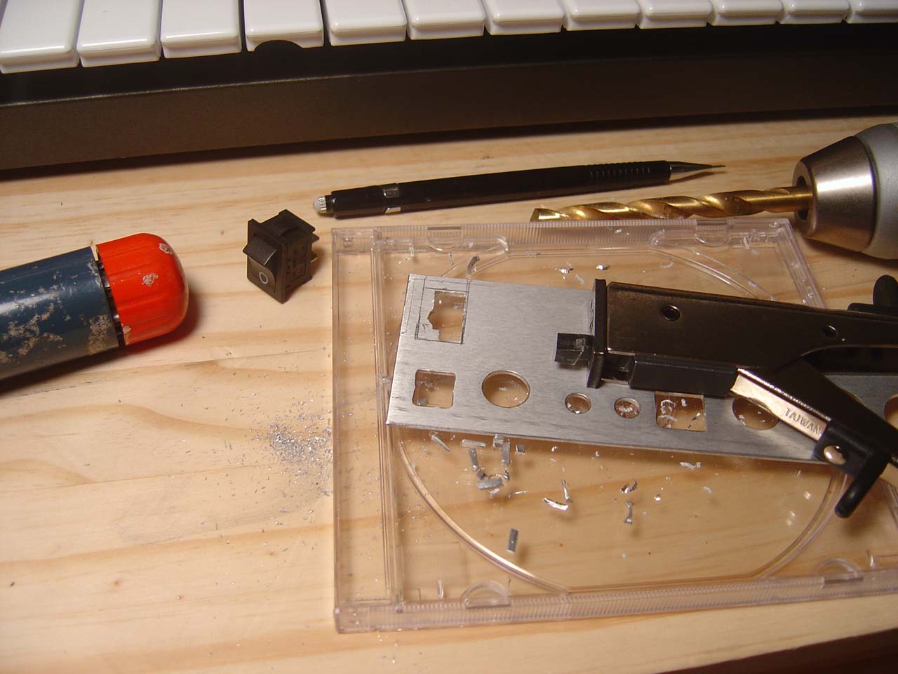
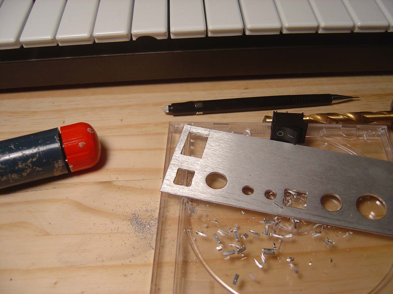

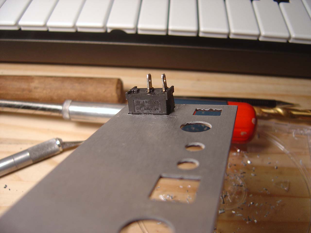
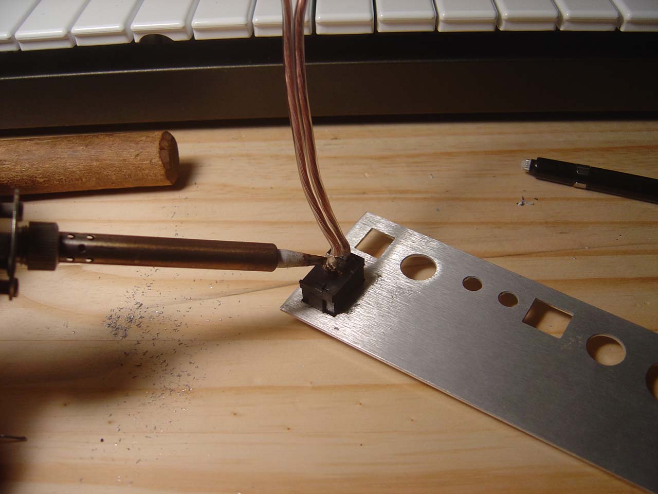


x0xb0x power switch mod - build steps
Thursday 02.28.2008
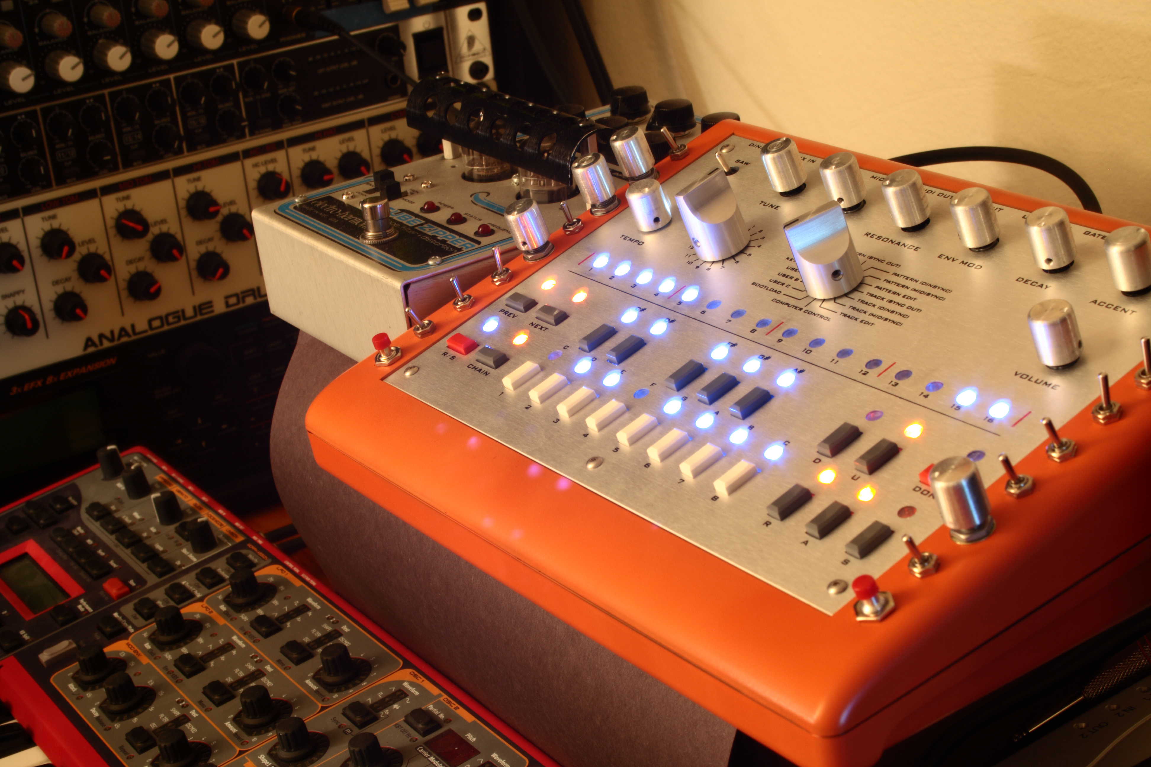
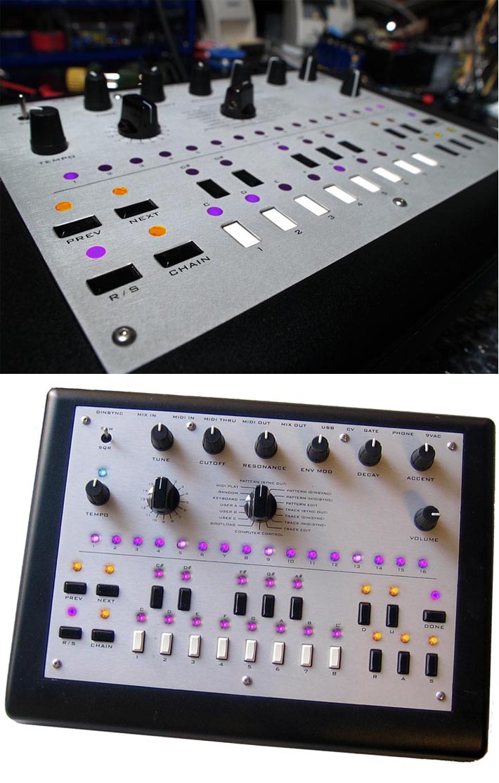
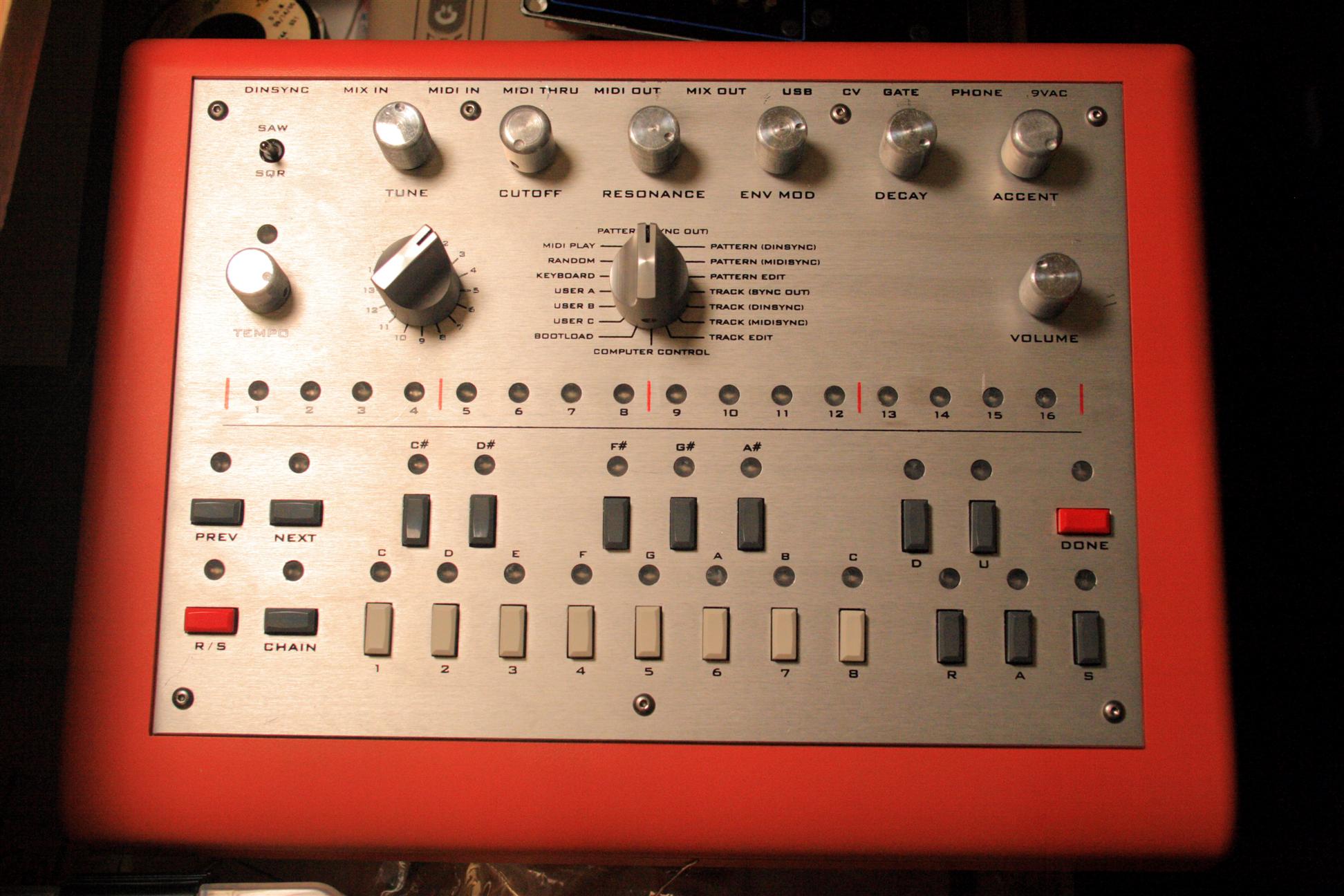
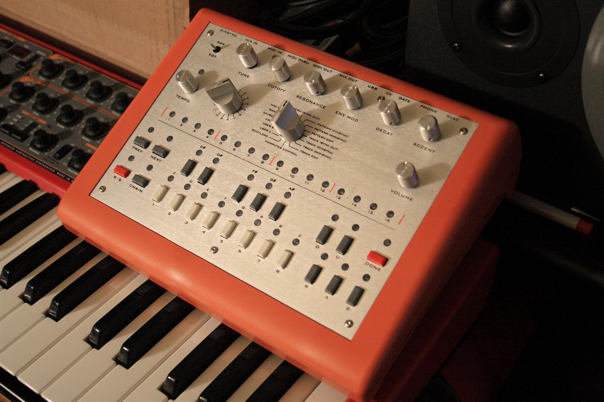
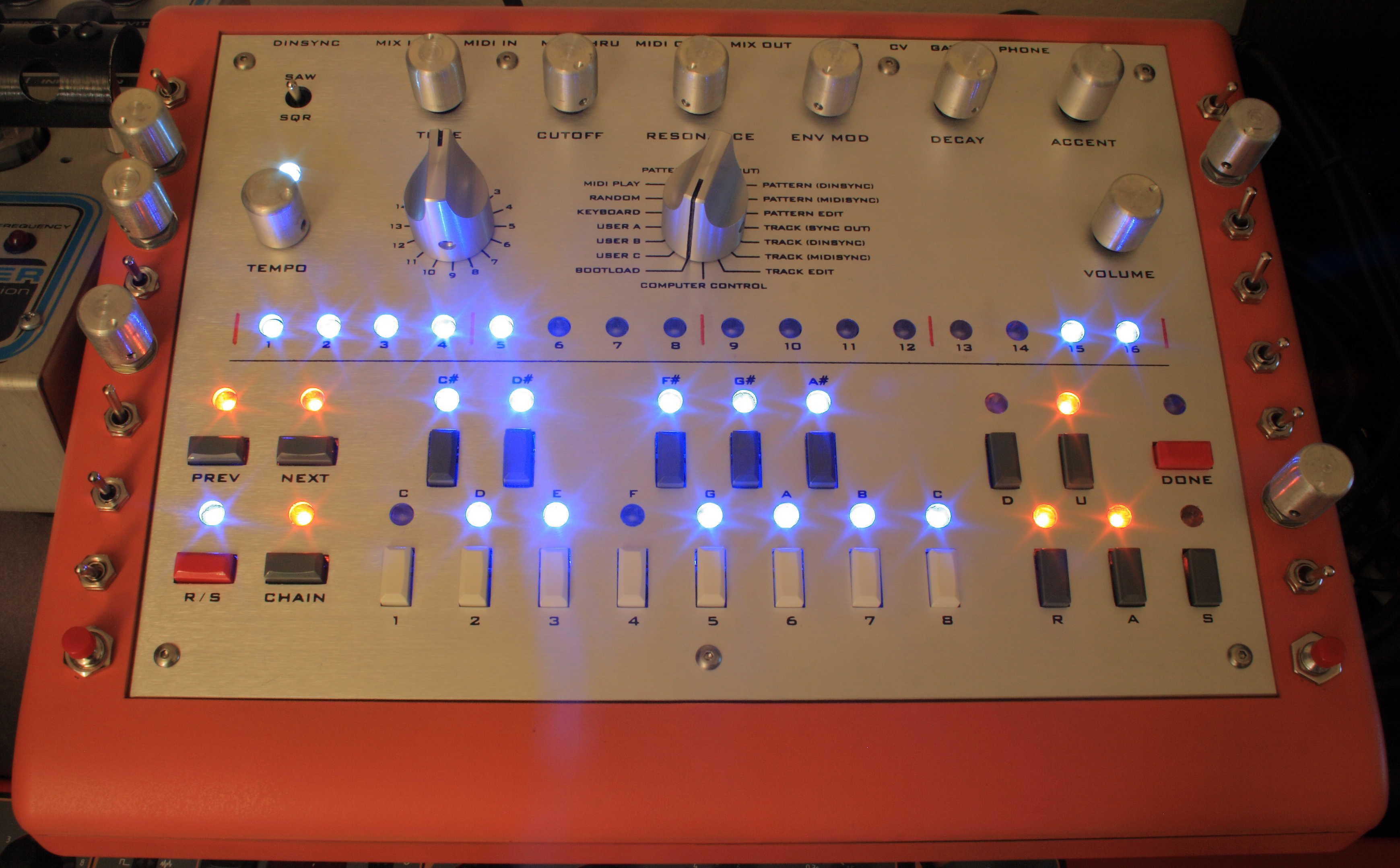
7:30-11am The x0xb0x got a makeover tonight. It's now got a new shiney silver and orange retro look. Orange Krylon Fusion paint, New aluminum knobs from Jameco and Digikey, and new button colors (red and grey) from Digikey. I took it all apart, and did several light coats of the orange paint so it wouldn't run. Check it out.
Sunday/Monday 05.18.2008
Sun 4-10pm, Mon 1-10pm ok, I got ambitious and added 18 new holes to the x0xb0x. But first I had to do a few things, 1.) I replaced the detented tuning pot with a non-detent one. The detent was very annoying when the tuning was only slightly off. 2.) I installed disconnectable cabling with polarized jacks (makes service a lot easier). Once those 2 maintanance issues were out of the way, it was time to dig in and add the mods (this list of mods is derived from the x0xd0x wiki).
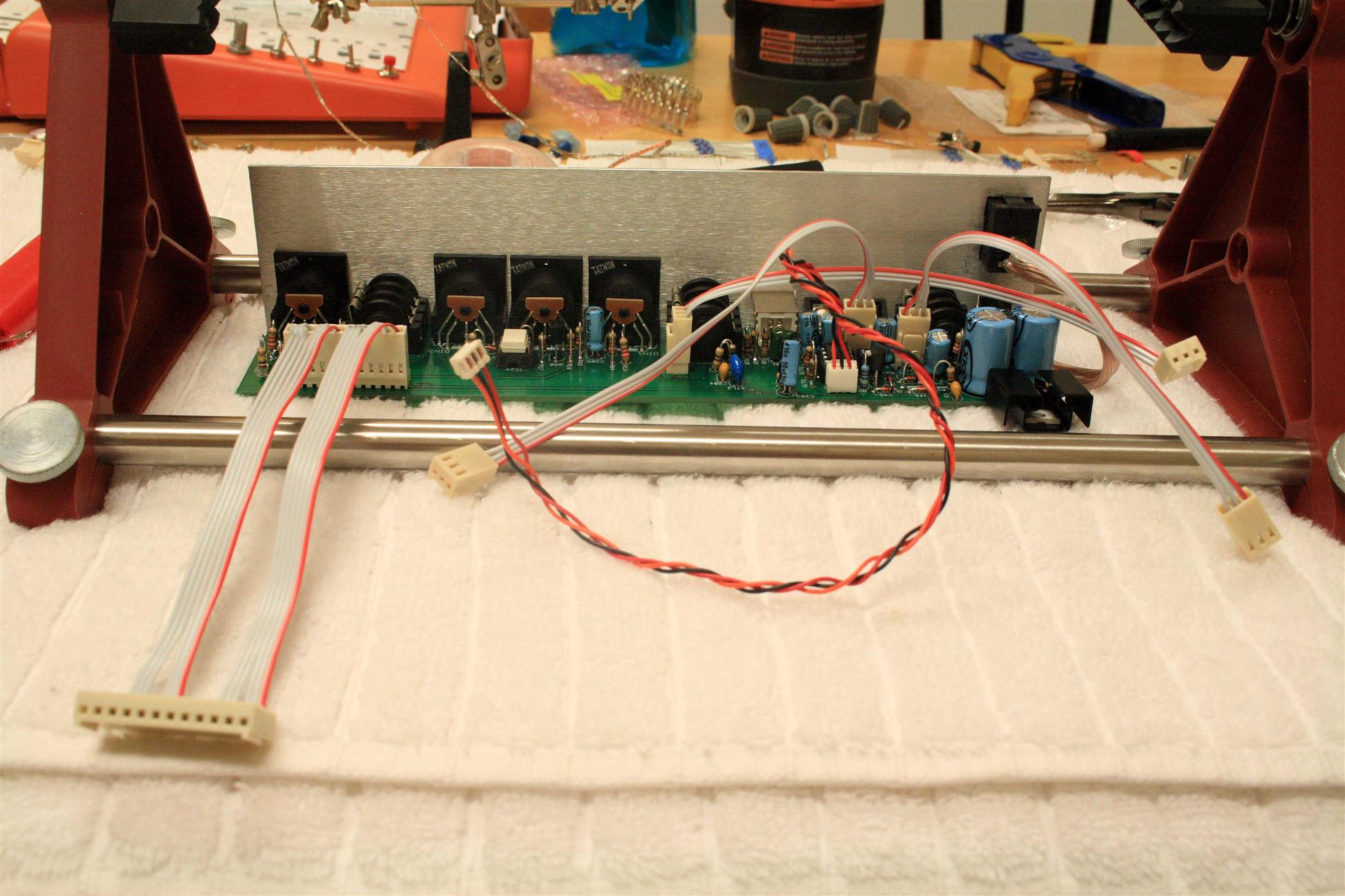
Polarized jacks and non-breaky ribbon cable
Makes the b0x easier to service in the future...
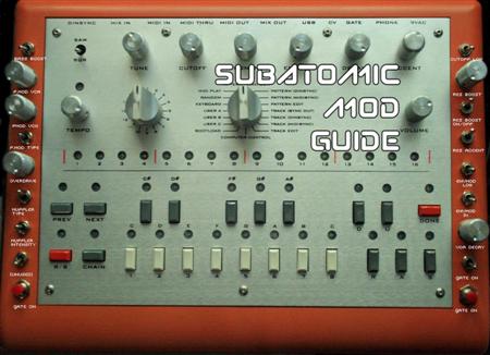
Getting ready (I printed my mod guide for convenience)
Here's the new UI (9 on each side):
|
|


Holes drilled, pots/switches installed
Check for clearance - looks good
time passes. many mods go in... a few tests are done, tweaks are made, and... done!
Mods done - kinda messy in there
Finished...
Sound Clips (with mostly qualitative descriptions...):
- (good diversity of mods shown here: frying pan insect buzzing zippering, massive distortion, groaning creaking rubber bands demonstrated)
- (pretty subtle use of mods here: drippyness and rubber bandy forever note slurring demonstrated)
- (pretty subtle use of mods here: bitcrusher-like sound, subtle filter mod effects, laser blasts, drippy squelches, thin broken speakers, rippy zipper, accent distortion demonstrated)
As you can see, many of the effects are subtle, they're still x0xb0x, but twisted
There's a few things I didn't get to, will do next time I open this up:
TODO:
- get a 2M pot for the VCA Decay (right now it's 1M pot in series with a 500k resistor, the decay is still very slow at 500k, so it'd be nice to go down to 0).
- swap location of envmod lower and envmod 3x (put "higher" above "lower", makes sense right?)
- 100kA log pot for the VCA filter modulation knob
- find something for the "unused" and "res enable" switch slots (really don't need the res enable)
- find something different for the left slap button. (maybe cutoff lowend, res accent boost, vca accent boost)
- labels!
Thursday 05.22.2008
12noon-6pm I'm releasing my mod guide which I used to help me mod my x0xb0x. I like using printed documentation when building my stuff, even if that means documenation I assemble myself, it really helps to have a good set of notes in printable form. :)
I've updated it with pictures and other notes from the procedure...