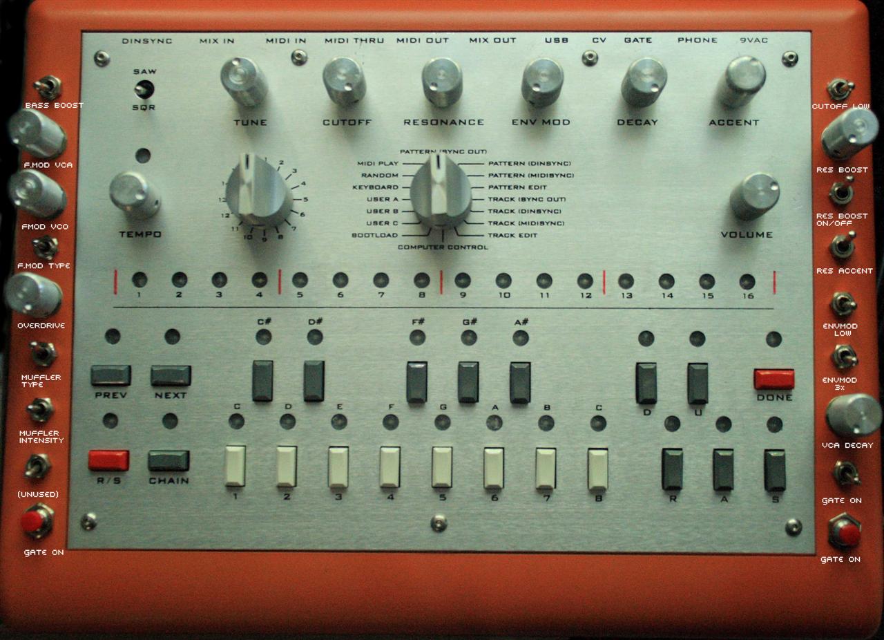
subatomic x0xb0x mod guide...
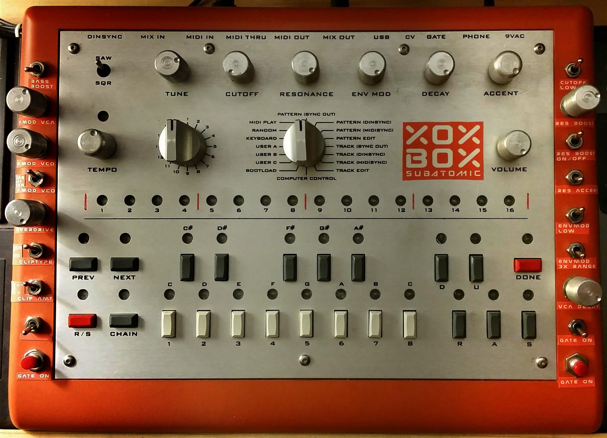
I created this guide to mod my x0xb0x as shown above, it's mostly cut-n-paste from the x0xd0x wiki, with several annotations, parts lists, wiring diagrams, and other clarifications made by myself...
Basically I did this so I could have a paper copy while I worked...
Feel free to integrate any of this info back up to the x0xd0x wiki.
The mods were selected for 1.) simplicity 2.) dramatic effect 3.) ability to turn off and return the x0xb0x back to stock (most important to me was to not lose the x0xb0x sound!). Total cost of parts are around $20-$30, and for this small amount, we get some nice additions to our x0xb0x arsenal, check out the sound clips
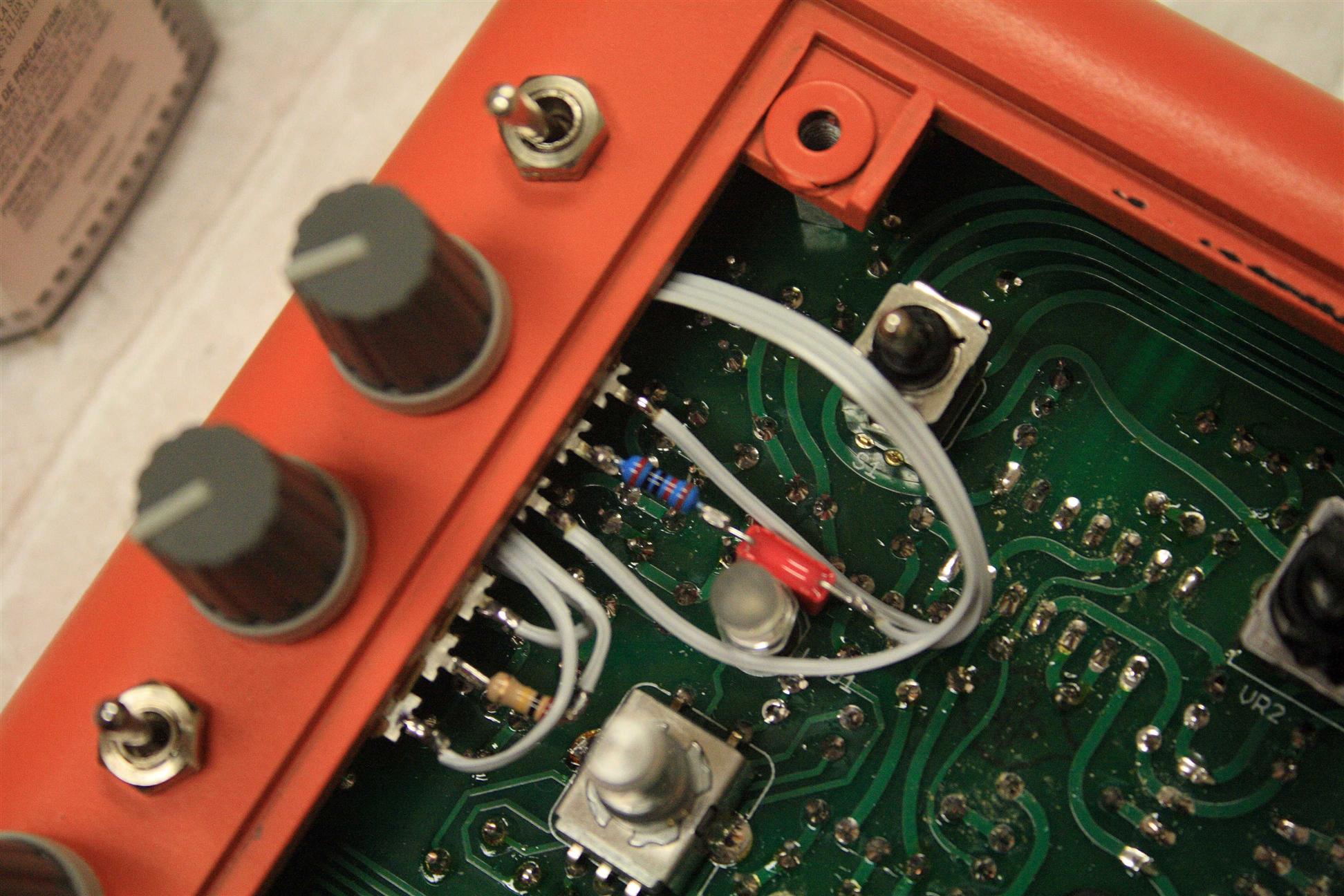
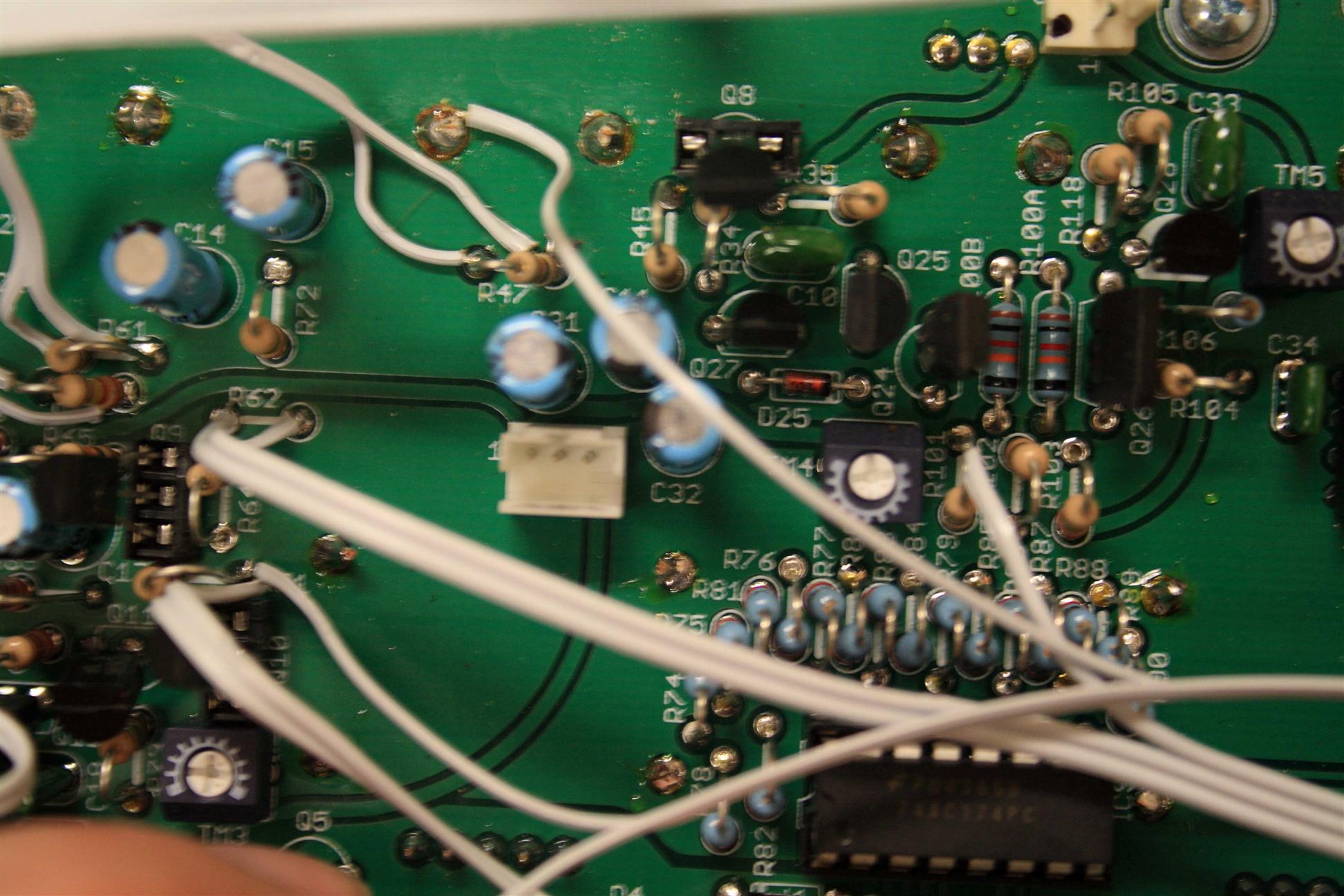
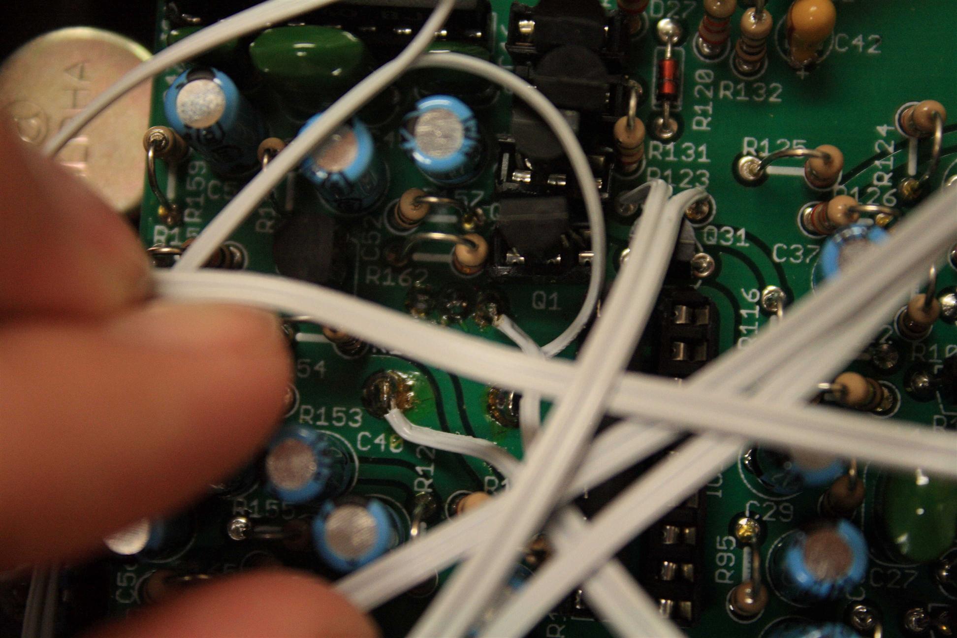
While modding my box, I took pictures, which you will find below at the appropriate places
Sound Clips (with mostly qualitative descriptions...):
- (good diversity of mods shown here: frying pan insect buzzing zippering, massive distortion, groaning creaking rubber bands demonstrated)
- (pretty subtle use of mods here: drippyness and rubber bandy forever note slurring demonstrated)
- (pretty subtle use of mods here: bitcrusher-like sound, subtle filter mod effects, laser blasts, drippy squelches, thin broken speakers, rippy zipper, accent distortion demonstrated)
As you can see, many of the effects are subtle, they're still x0xb0x, but twisted
Table of Contents
Cosmetic: Functional:- Bass boost mod
- Env Mod Amount
- Increased Filter Low End
- Resonance Boost
- VCF External In
- Res tuning trim pot
- power on/off switch.
- VCA Envelope On Forever
- Variable VCA Decay
- Filter Modulation (VCO)
- Filter Modulation (VCA)
- Filter Overdrive
- Muffler like Distortion
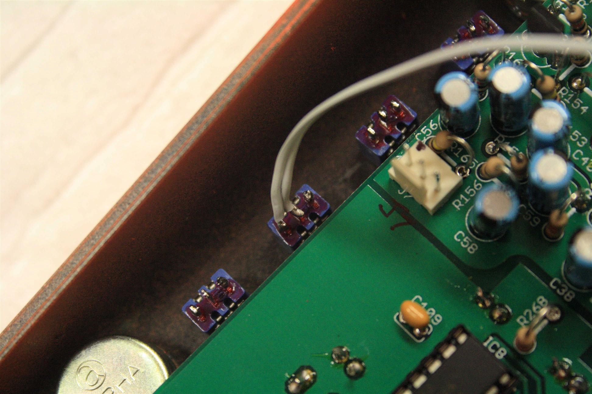
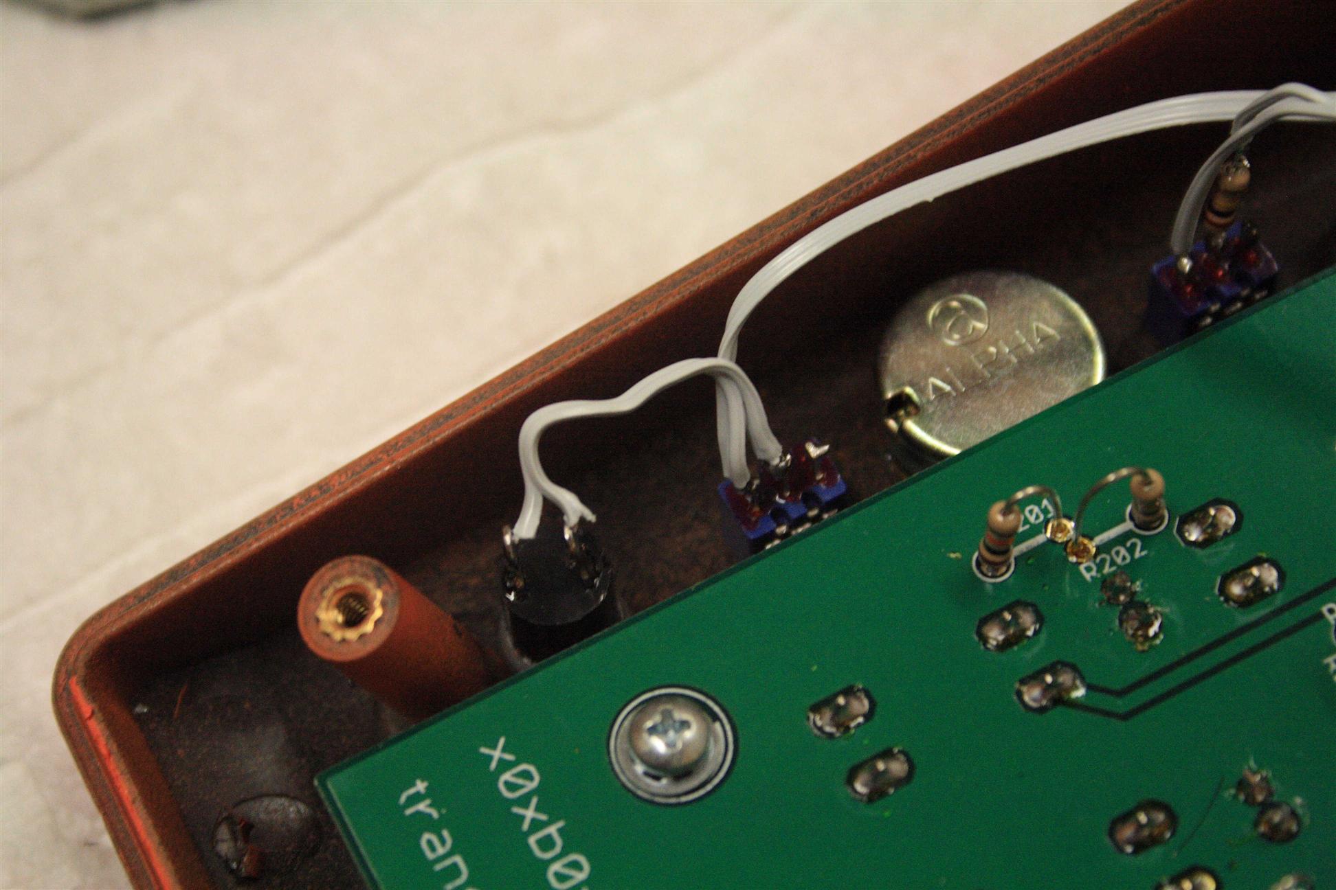
PolarizedJacks
If you're going to work on your x0xb0x (you will be if you're modding it), then you'll want to take it apart. I use Molex .100 headers and connectors from Mouser (Futurlec has the same thing, but for less).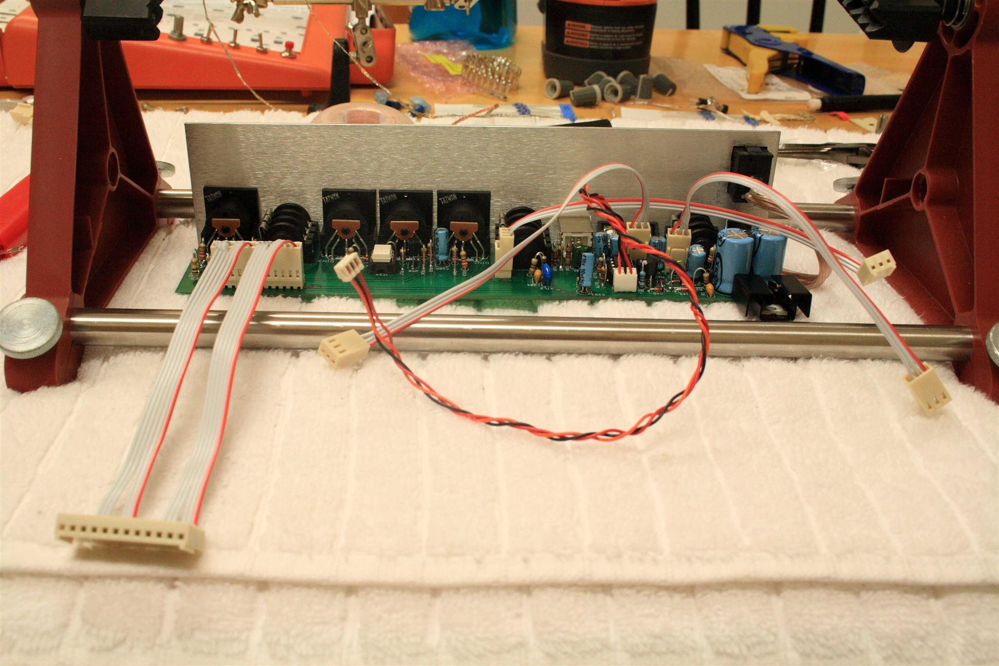
3pin (mouser):
538-22-23-2031 3pin Header
538-22-01-2037 3 pin connector
538-08-50-0114 Molex crimp pins
Using these links, search on the catalog page for the 12pin ones, get the right-angle kind for the main board so your case closes tight (I found out after I soldered mine, so I had to trim some plastic off the connector to make it have enough clearance...) maybe order both kinds (straight and right angle) just in case...
Molex connectors at Futurlec:
these are identical to the Molex ones from mouser, and way cheaper. I recommend them. Mouser ships faster though.
See my Tutorial on making cables
Paint
I used Krylon Fusion Pumpkin Orange...Many light coats to prevent running (around 6-9).

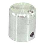
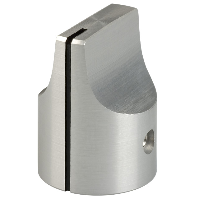
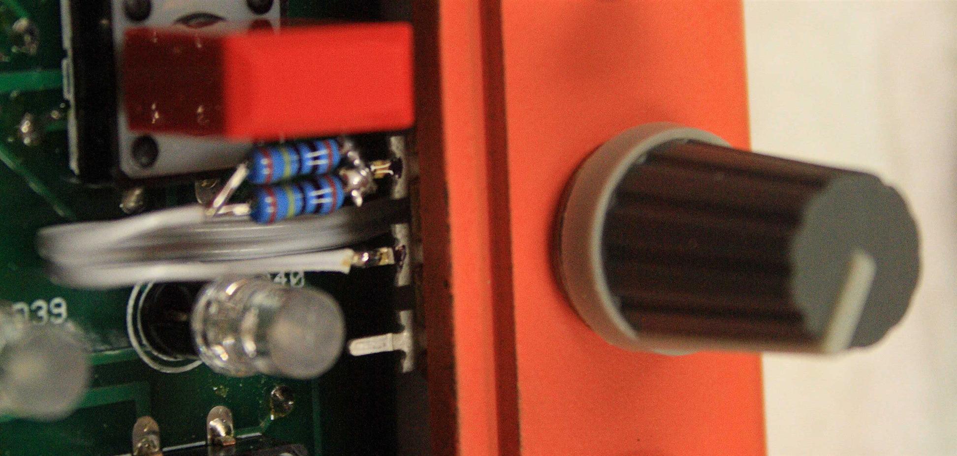
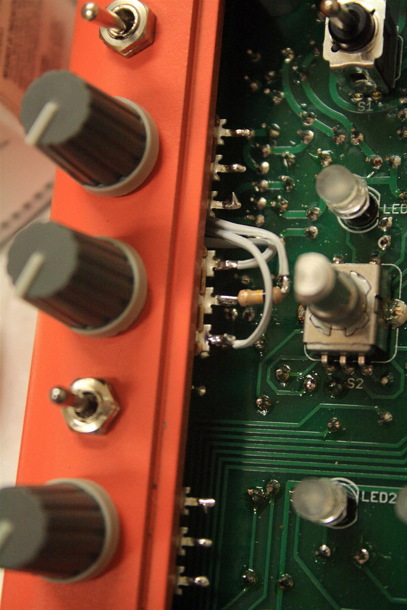
Knobs & Buttons
Parts List:- Small knobs: JAMECO VALUEPRO K5-1/4S p/n 162481 - .500"H x .560"Dia. 1/4" shaft with set screw.
- Big Knobs: Digikey KILO HD-75-1-5 .75" dia, .25" shaft.
- Red/Grey Switch Caps: Digikey C&K "PE GY" (401-1153-ND) and "PE RD" (401-1154-ND)
Labels
Labels for the x0xb0x.at 300dpi...
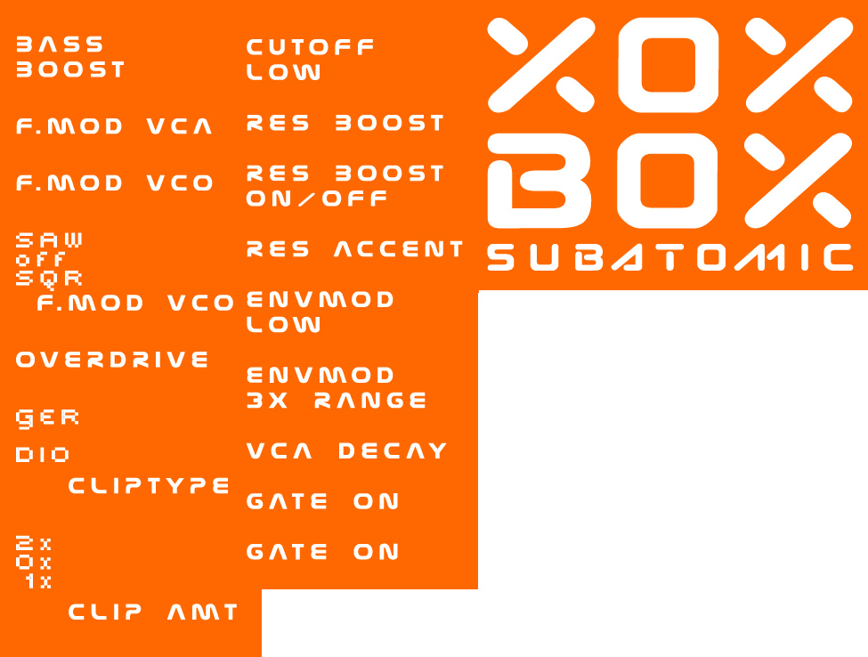
Layout for the mods.
Layout for the labels.
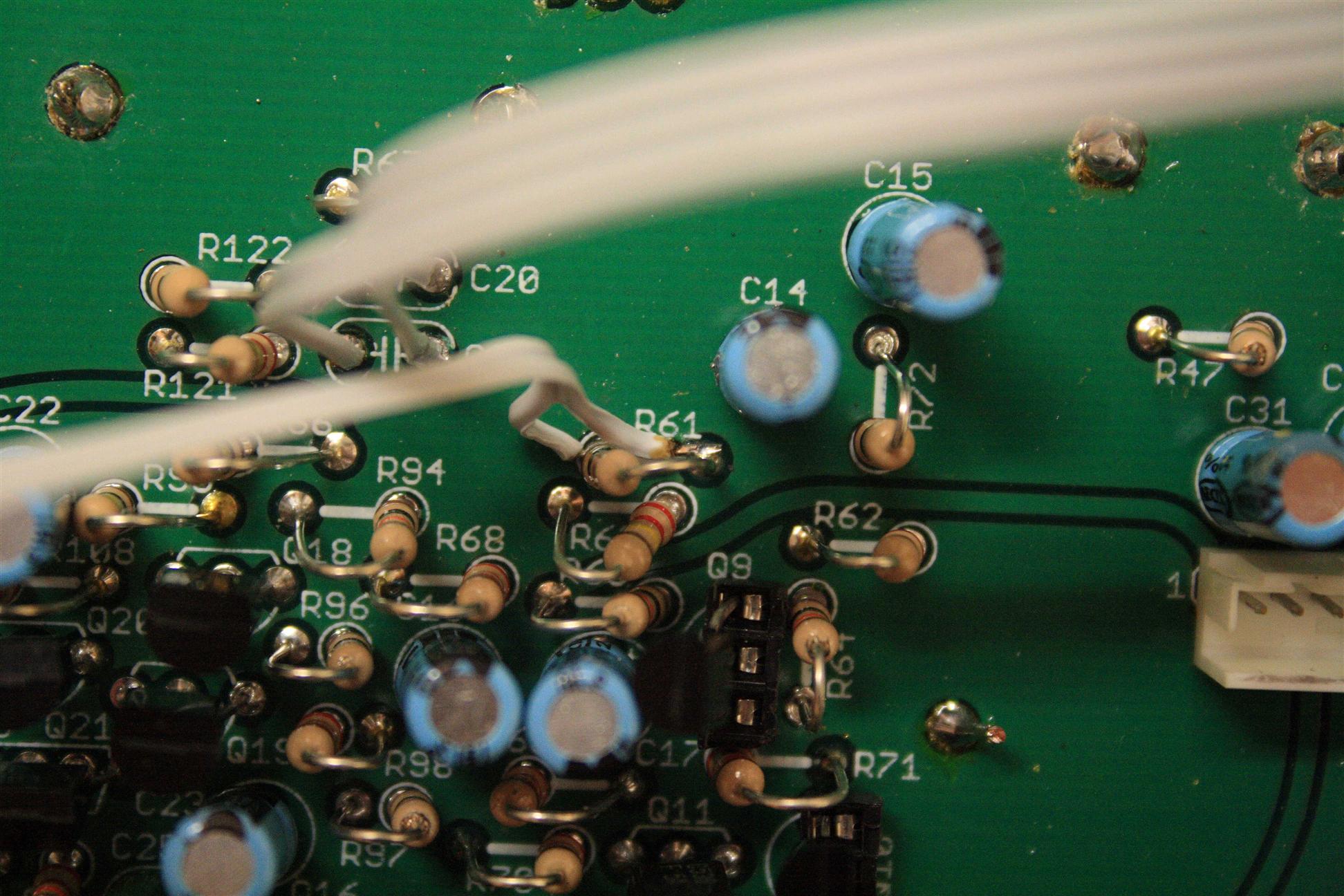
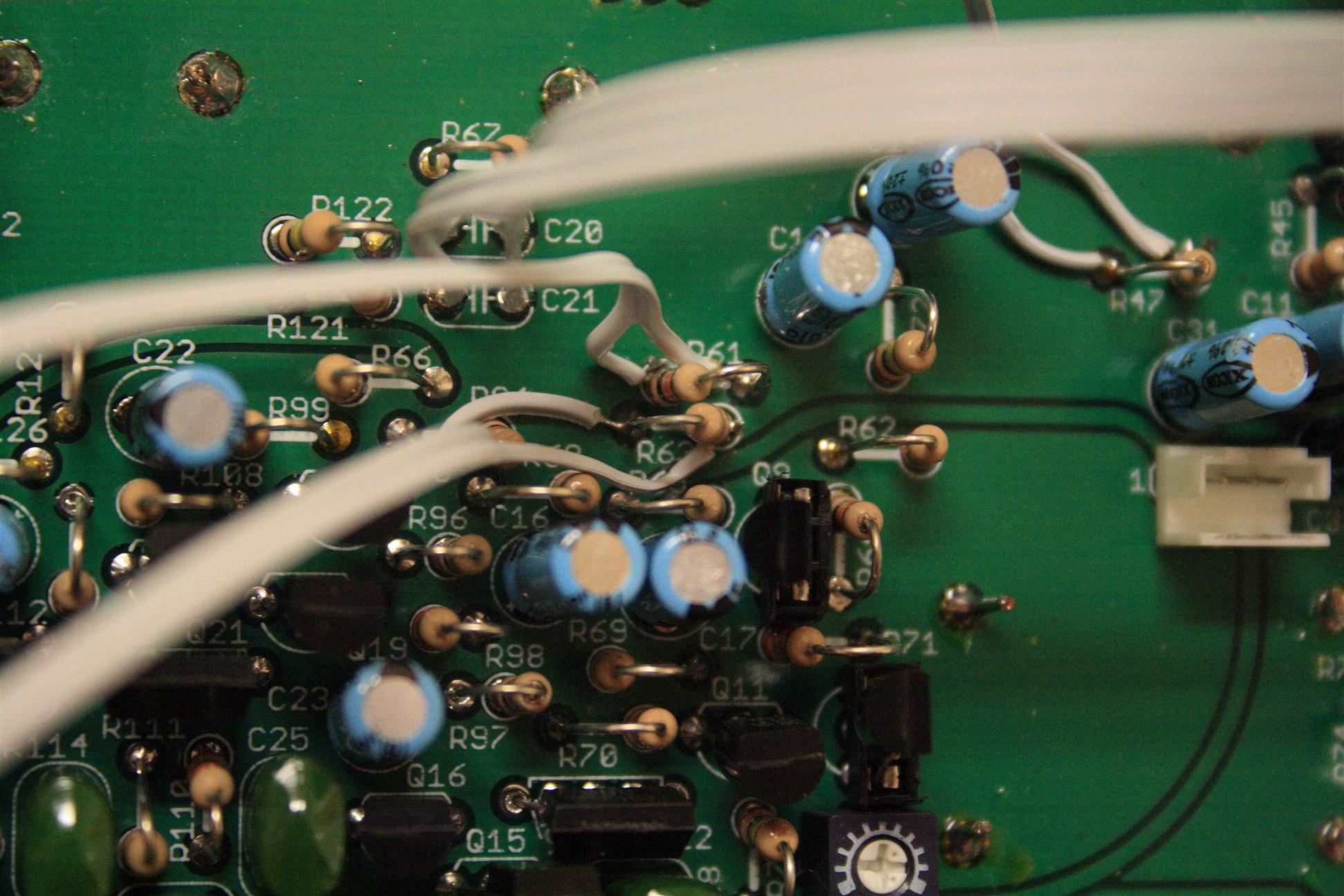
Bass boost mod
This mod is absolutely essential if you want your x0xb0x to be a bassline machine. It is a really good one to make! Change C21 and C20 from .01uF to .1uF. Some people have found that it gets too boomy if you use your x0xb0x for more of a lead sound, but you can usually roll off the bass on your eq instead. Parts List- 2x .01uF cap (old one in x0xb0x, might need a new one with longer leads)
- 2x .1uF cap
- DPDT switch on-on (to select between old caps (normal), and new caps (bass boost))
 switch pinL1 - .1uF
 switch pinL2 - .1uF
 switch pinR1 - .01uF
 switch pinR2 - .01uF
 switch pinC1 - C21 (pin1)
 switch pinC2 - C20 (pin1)
 .1uF - C21 (pin2)
 .01uF - C21 (pin2)
 .1uF - C20 (pin2)
 .01uF - C20 (pin2)
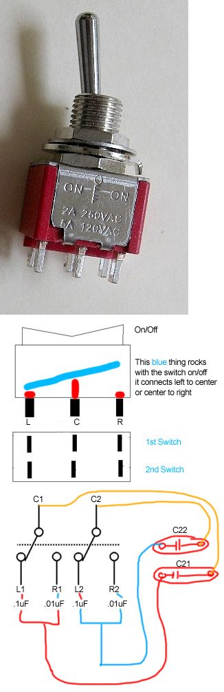
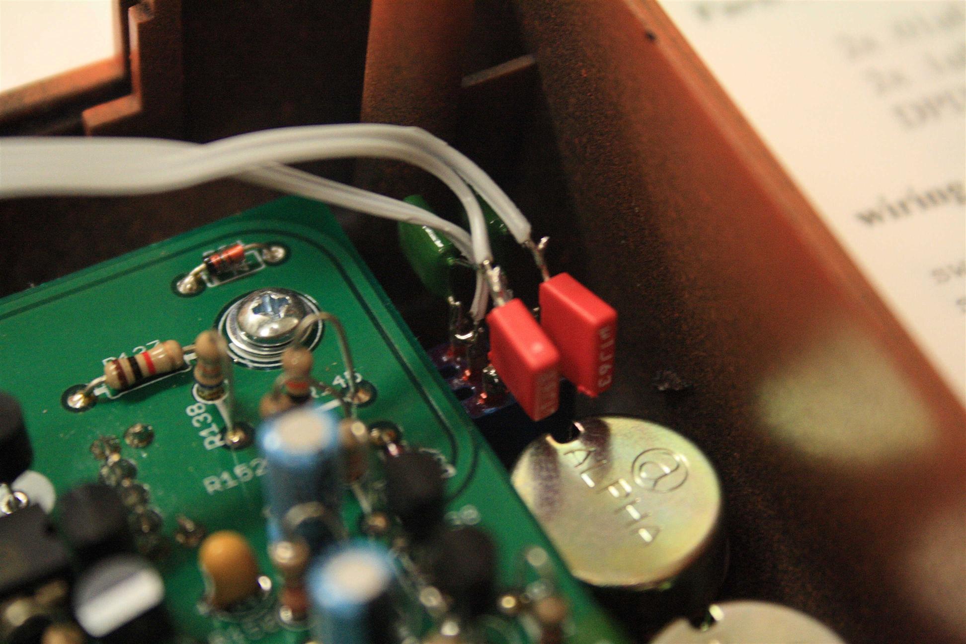
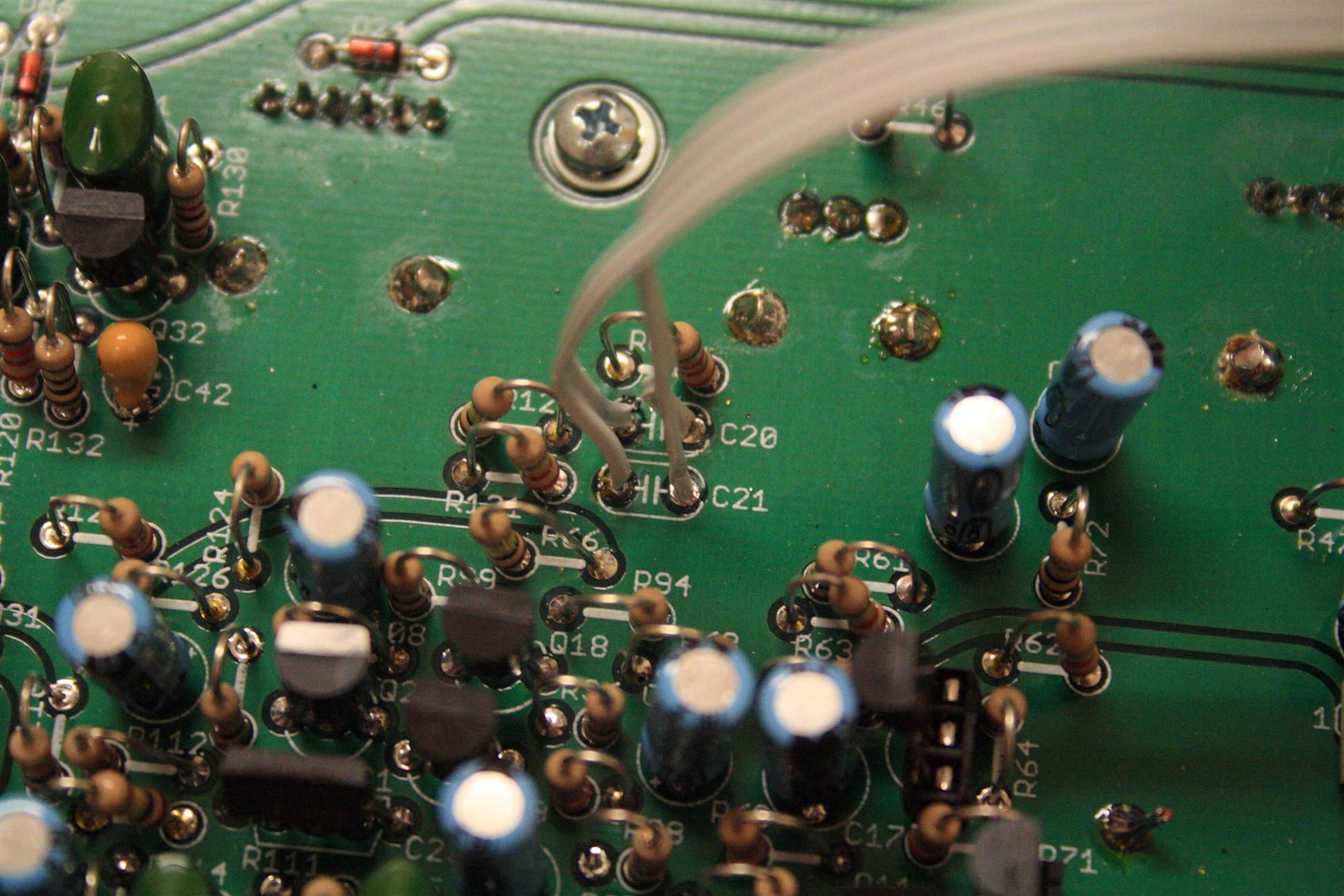
bass boost
Env Mod Amount
Thanks to RobinWhittle of the DevilFish for posting these mods on his site. Turning it all the way downRemove R61 and replace it with a jumper wire. This will make it possible to turn the envelope modulation all the way down. If you want to make it switchable, leave R61 in place and solder a wire from each terminal of R61 to a switch. This will enable you to shorten out R61, much like replacing it with a jumper wire. Increasing the range by 3 times
Add a 100K resistor in parallel with R63. Easy. [This basically reduces the resistance to ~68.75K, 1/3 the original value.] Parts List
envmod all the way down:
- some jumper wire
- switch SPST on-off
- 100k ohm resistor
- switch SPST on-off
envmod all the way down
hook this switch to R61
- center post of spdt switch to one side of R61
- "on" post of spdt switch to other side of R61
envmod extend to 3x the range
hook this switch to R63 (with a 100k in line)
- center post of spdt switch to 100k, then to one side of R63
- "on" post of spdt switch to the other side of R63
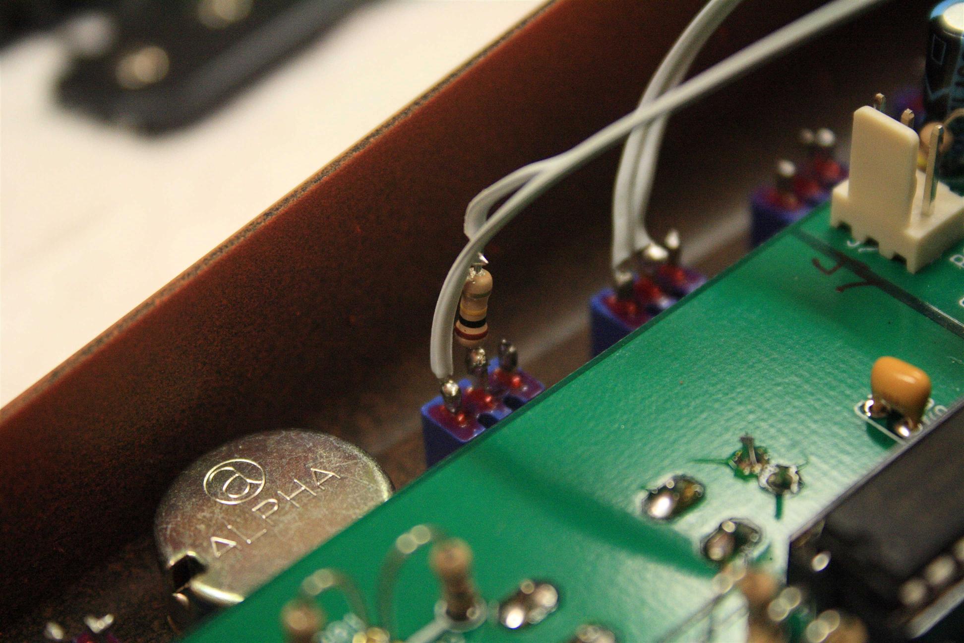
Increased Filter Low End
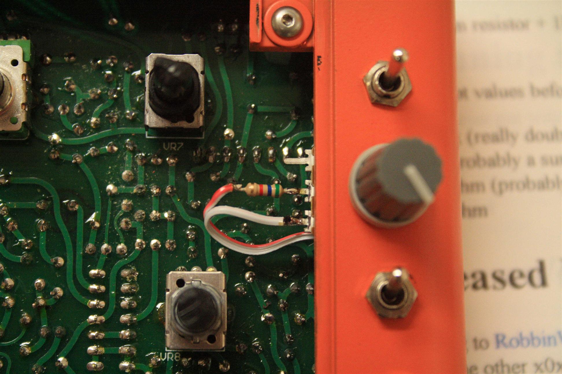
According to RobbinWhittle, all you have to do is short out R47 (10K ohm resistor) by a length of insulated wire. Some other x0xers tried it out, and found that mounting a 4.7K ParallelResistor along with R47 works better (giving 3197 ohms resistance). This will also affect cutoff range to a degree Parts List- jumper wire
- 4.7k resistor
- switch SPST on-off
cutoff lowend
Resonance Boost
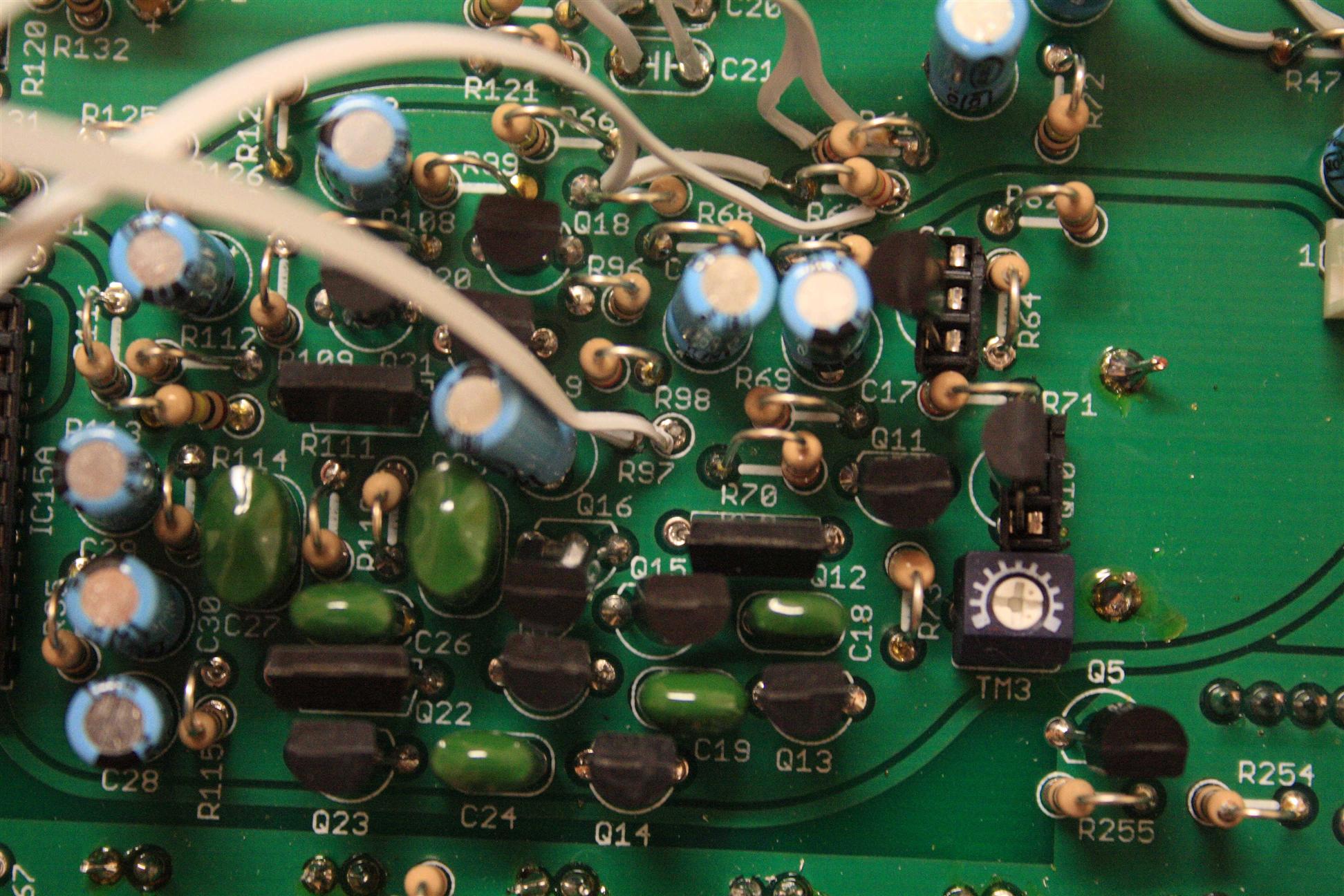
You can change the value of some of the resistors on the VoltageControlledFilter to boost the resonance.- Decrease R97 to ~7.5K
- Decrease R108 to ~1.8K
- Decrease R112 to ~5K
- Increase R109 to ~22K (perhaps even larger?)
The plan is to replace R97 only, controlled by a single "boost" pot:
- 5k resistor (4.7k, or 5.6k)
- 5k pot - to go from 5k to 10k
- optional. SPDT switch on-on (for switched on or off)
Resonance boost switch to enable/disable, you could replace the 5k + 5.6k section by any value...
switch is optional if using a pot that defaults at 10k...
              ______
             v      |
  SPDT /o--/\/\--   o--/\/\--o
.-----/     5k          5.6k  |--o
|       o--/\/\--------------o    R97
|          10k
'--------------------------------o
Resonance Boost
resonance accent increase
short out r46 to increase the resonance accent.
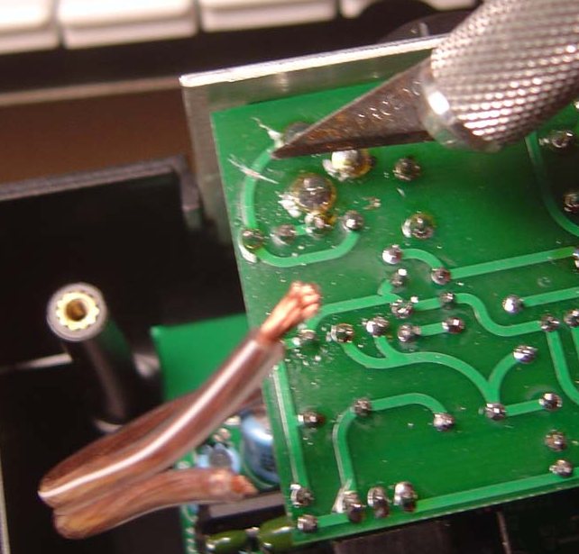
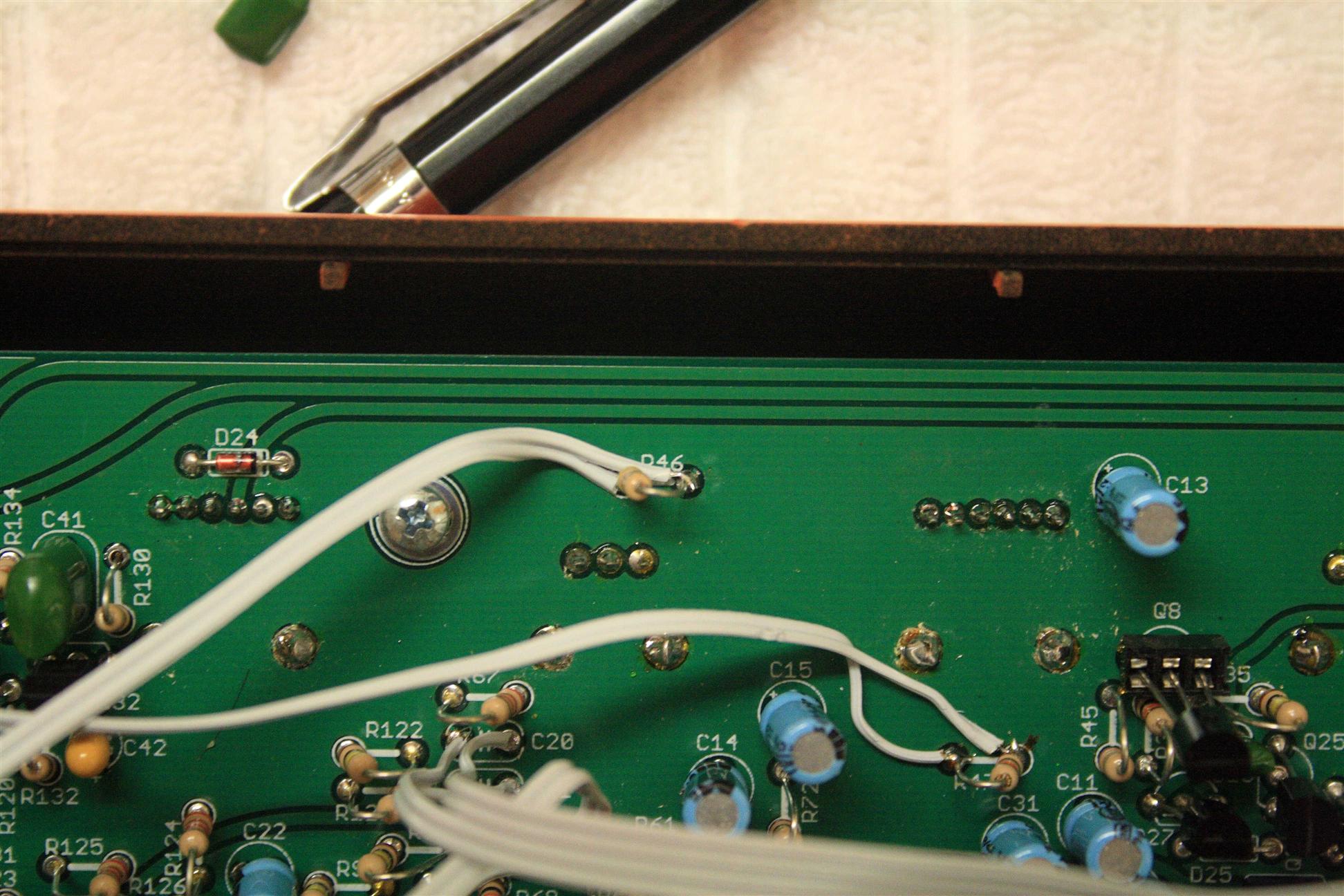
Resonance Accent Increase
power on/off switch.
This lets you turn the x0xb0x on/off without unplugging the power cable. Just cut the trace coming from the 9VAC power plug, and insert a switch there. Parts List- on/off rocker switch
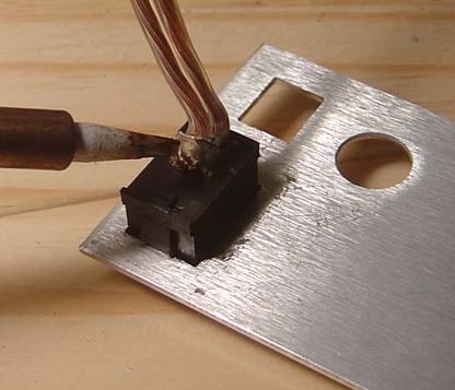
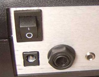
Power Switch On/Off
[Env mods]
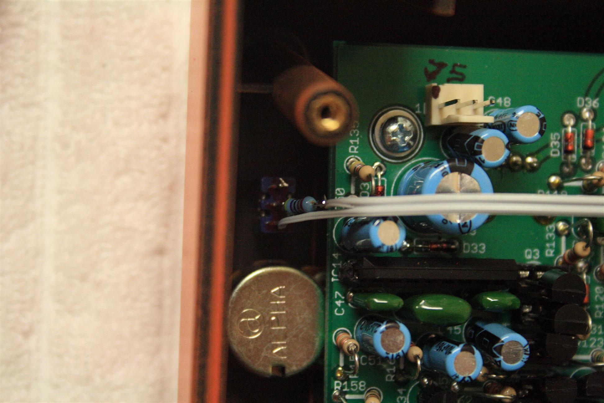
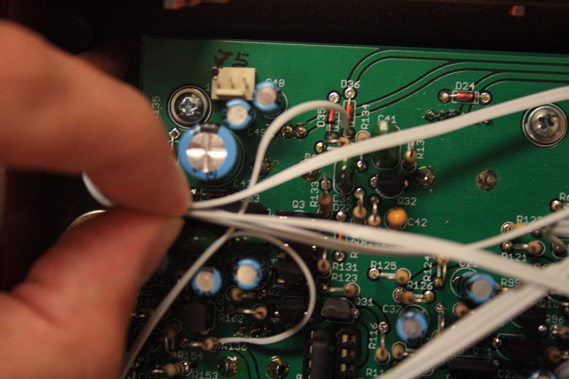
VCA Envelope On Forever
Tie a line from the juncture of D36 and R134 to a single pole switch, and the other end to 12V. When the switch is on, your notes will be on forever Parts List- SPST on-off switch
SPST switch puts 12V onto D36/R134 when on:

  D36      R134            R136
--->|--o---/\/\/--o     --/\/\/--o---|> 12V
       |                         |
       |                         |
       o     o                   |
        \                        |
         \                       |
          |  SPST on/off         |
          |                      |
          o----------------------+
VCA Envelope On Forever
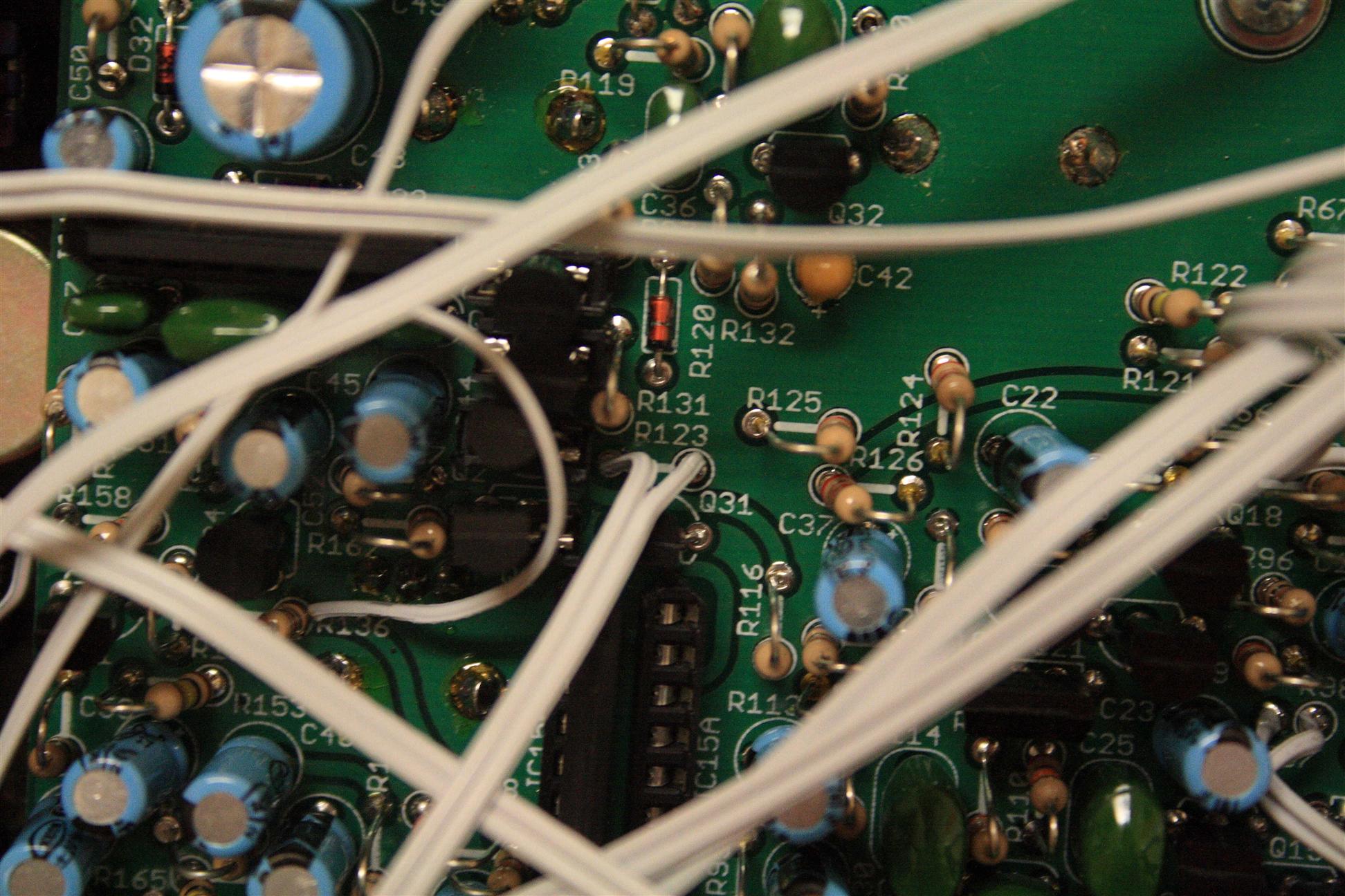
Variable VCA Decay
r123 controlls the decay of the VoltageControlledAmplifier, replace this with a pot to get variable decay.Replace the r123 1.5M resistor with 1M pot in series with 500k resistor (or ideally use a 2M pot and no resistor): Parts List
- 1M pot
- 500k resistor
- Optional: 2M pot (may need to add some small resistor value in series with this, untested)
Notes: the decay is loooong. you'd probably be fine using 1Mpot directly (and possibly add in a small value in series). I doubt you'd miss the long falloff of 1.5M... just an idea.
Variable VCA Decay
Filter Modulation (VCO)
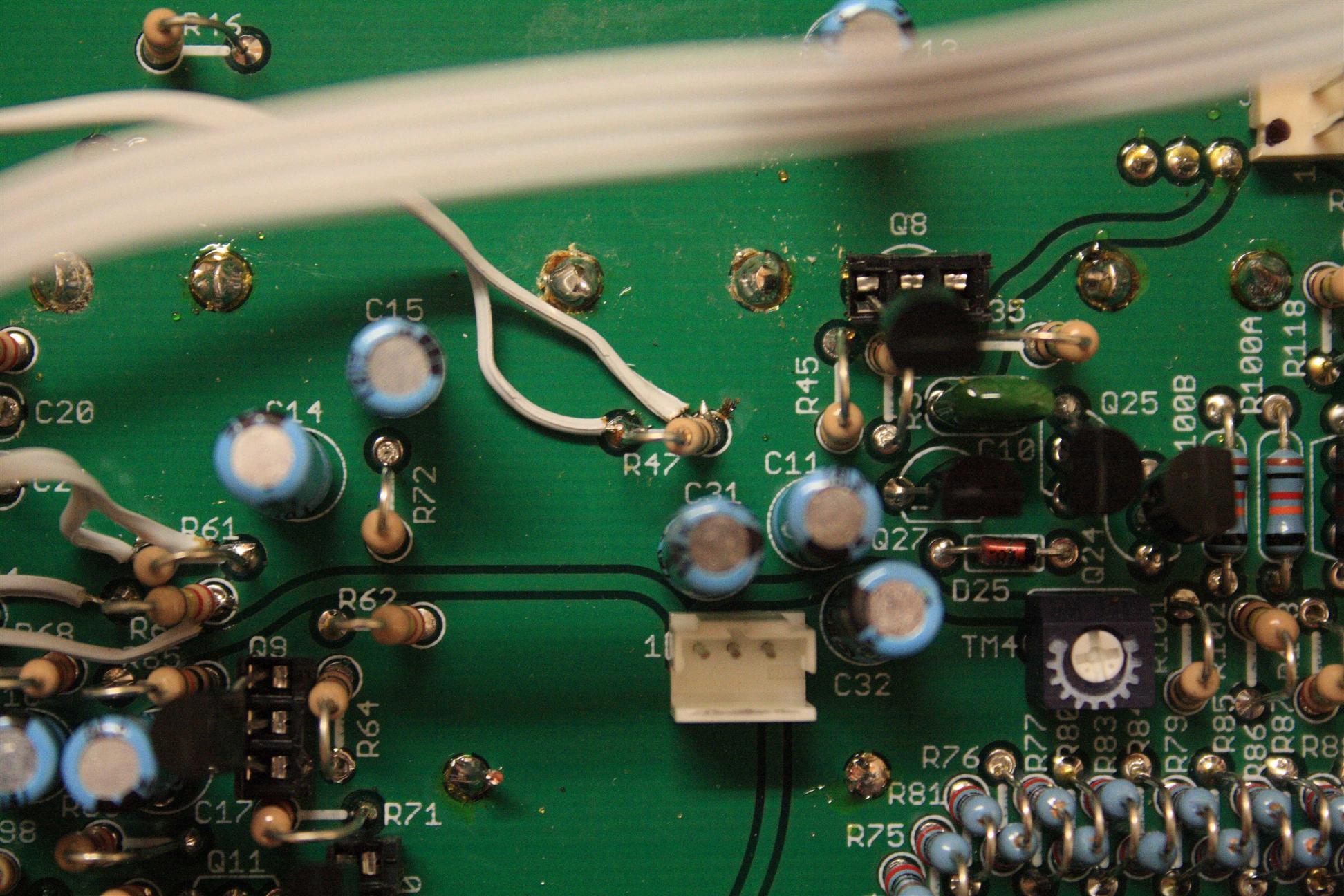
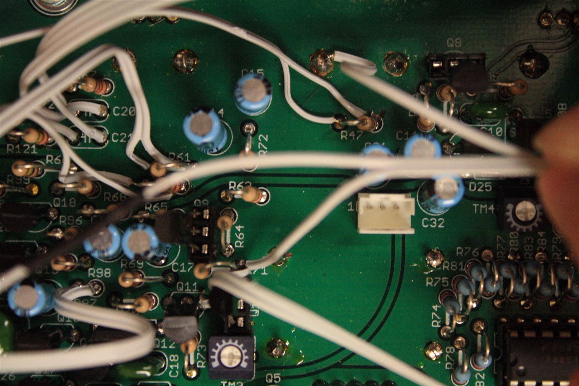
This is another relatively easy but awesome mod for the 303. Take the feed from the square wave (R36/Q8) and the saw wave (R105/Q28) and wire one to pin3 of an SPDT switch and the other to pin1 of the same switch. Use a SPDT switch so that you can select the saw or square wave as the modulation source. Take pin2 from the switch to the 3rd leg of a 50K log pot. Wire the first leg of the pot to the junction of R71/Q9/Q11 (the is a reference voltage for VCF-Mod - see page 8 in the 303 service manual: http://dl.analoghell.com/index.cfm?id=107). From the middle leg of the pot hook up a 100k resistor. Wire the other end of the resistor to the junction of R71/R72/Q10-base, the summing point for the filter frequency input. This will let you select the saw or the square as the modulation source independant of the what you have selected for the VCO. Depending on where all the other controls are set you can get everything from an evil zipper to slowly dripping acid - among other things! Parts List- wire
- SPDT on-off-on (filter mod waveform select)
- 50k log pot (filter mod amt.)
- 100k resistor
 SPDT pin1 - R36/Q8 - square wave source
 SPDT pin3 - R105/Q28 - saw wave source
 50k pot pin3 - SPDT pin2 - selected wave form...
 50k pot pin1 - R71/Q9/Q11 - reference voltage
 50k pot pin2 - 100k res - R71/R72/Q10-base - summing point for filter frequency input
  SPDT     /-o1 SQR R36/Q8   (waveform switch)
      2o--/
       |     o3 SAW R105/Q28 (waveform switch)
       |
       o 3
       |
       /
   50k \<-o-----/\/\/---------o R63/R72/Q10/R71  (summing point, filter input)
   pot /     2  100k          \
       |                      / R71
       o 1                    \
       '----------------------o Q11/Q9/R71
Notes: the latest x0xd0x wiki calls for a 100nF cap in series with the 100k. I tried this and the effect was much more quiet (undesirably so). I'm guessing the 100nF cap is to buffer the signal... The mod works better without the 100nF.
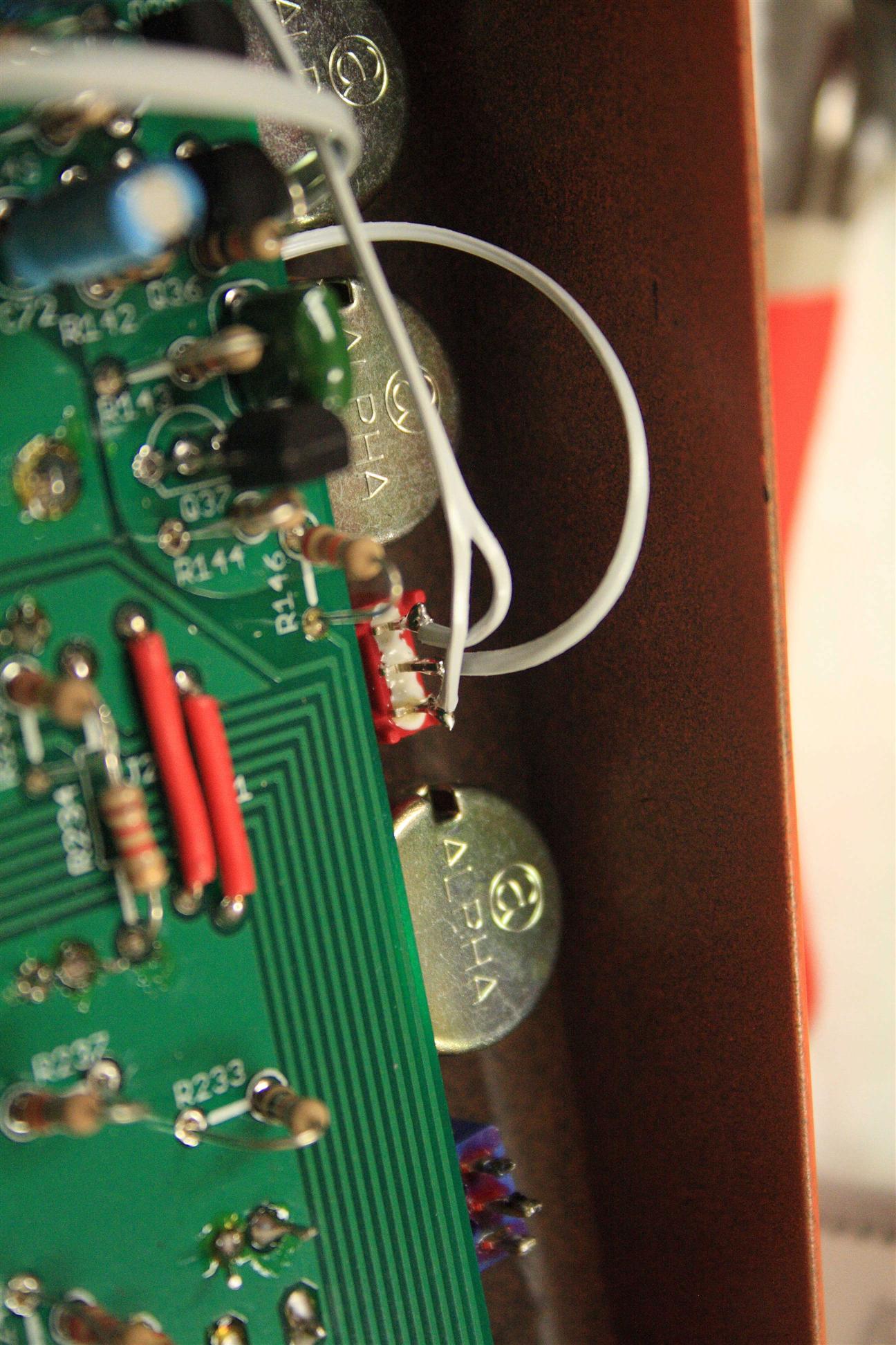
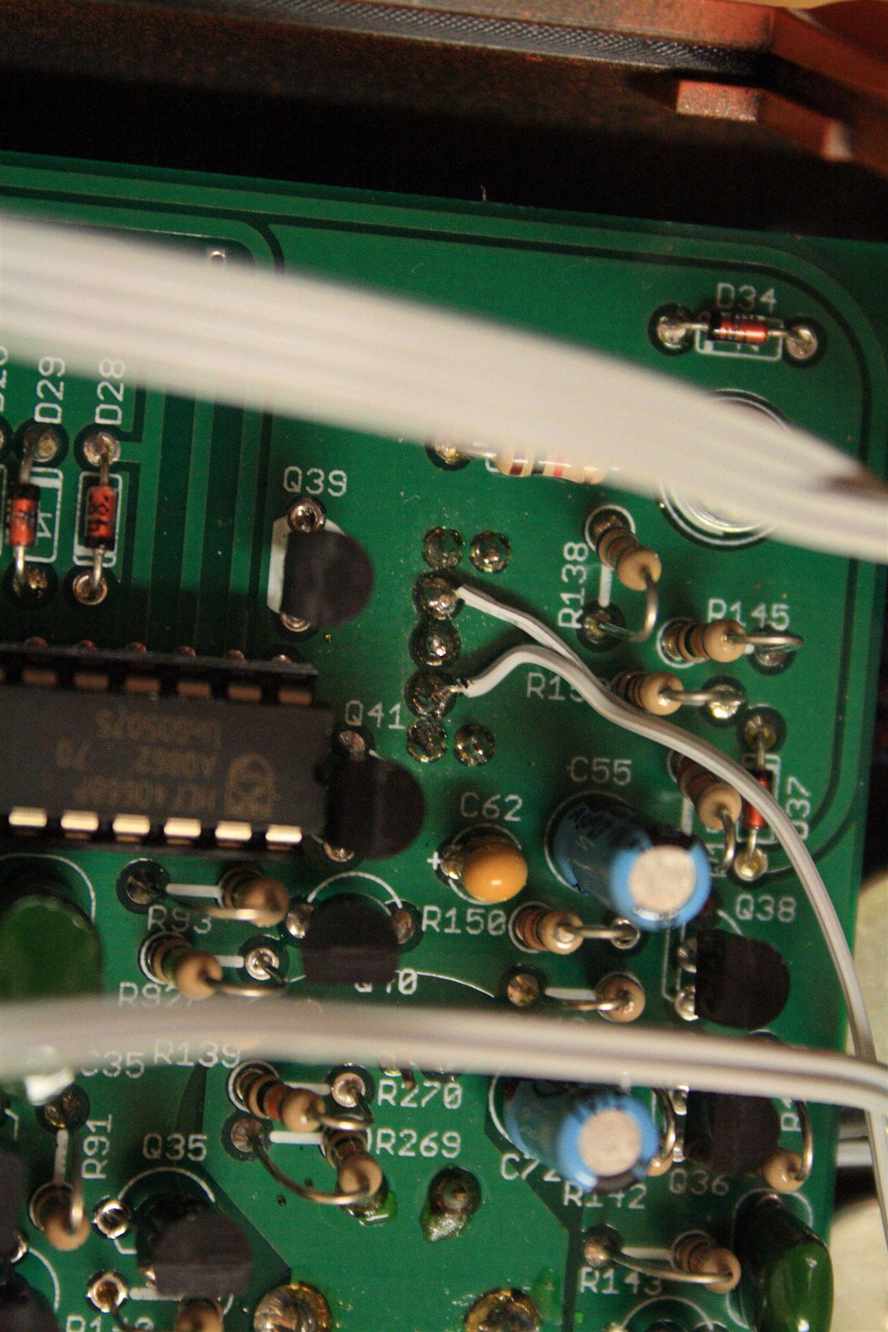
Filter Modulation VCO Source Selector
Filter Modulation VCO Amount
Filter Modulation (VCA)
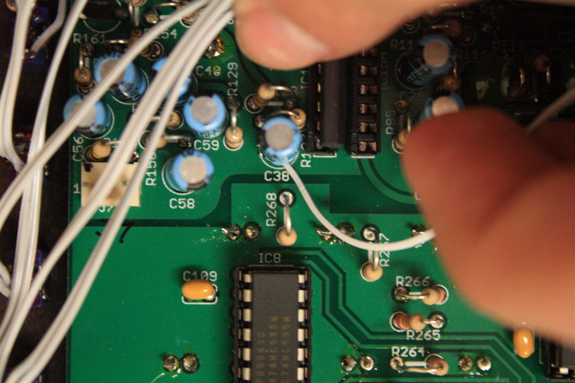
same as above. Instead this time you’re taKing the signal from the VCA out (C38). I get the best result with the following... Parts List- 100kA (log) pot
- 100nF cap
- 20k resistor
- optional: 47nF cap
- optional: 62k resistor
 100k pot pin3 - C38                       (VCA output)
 100k pot pin1 - GND                       (no sound)
 100k pot pin2 - 100nF - 20k - R71/R72/R63 (summing point for filter frequency input)
    C38(-)  (VCA output)
      o
     3|
      /   100nF   20K
100kA \<-o-||---\/\/\/--- to R72/R71/R63 (summing point for filter frequency input)
 pot  / 2
     1|
      o
     GND    (no sound)
Notes(1): get GND from one of the VRx pots on the mainboard... connect to the pot's case pin. These all seem to be grounded, but check to be sure in case future revisions of the mainboard change.
Notes(2): 100nF was 47nF on jonnay's wiki, wonder why this changed? I tried both 47nF and 100nF and couldn't tell a difference (I recorded both signals and A/B'd them to be sure).
Notes(3): also this text was deleted from the above paragraph... I found with this mod you get the full modulation with the pot at max when using about a 62K resistor back to the summing point of R71/R72/R63(as opposed to 100K). strange... I did not try 62k, i'm assuming the cap is to buffer the signal.
Filter Modulation VCA Amount
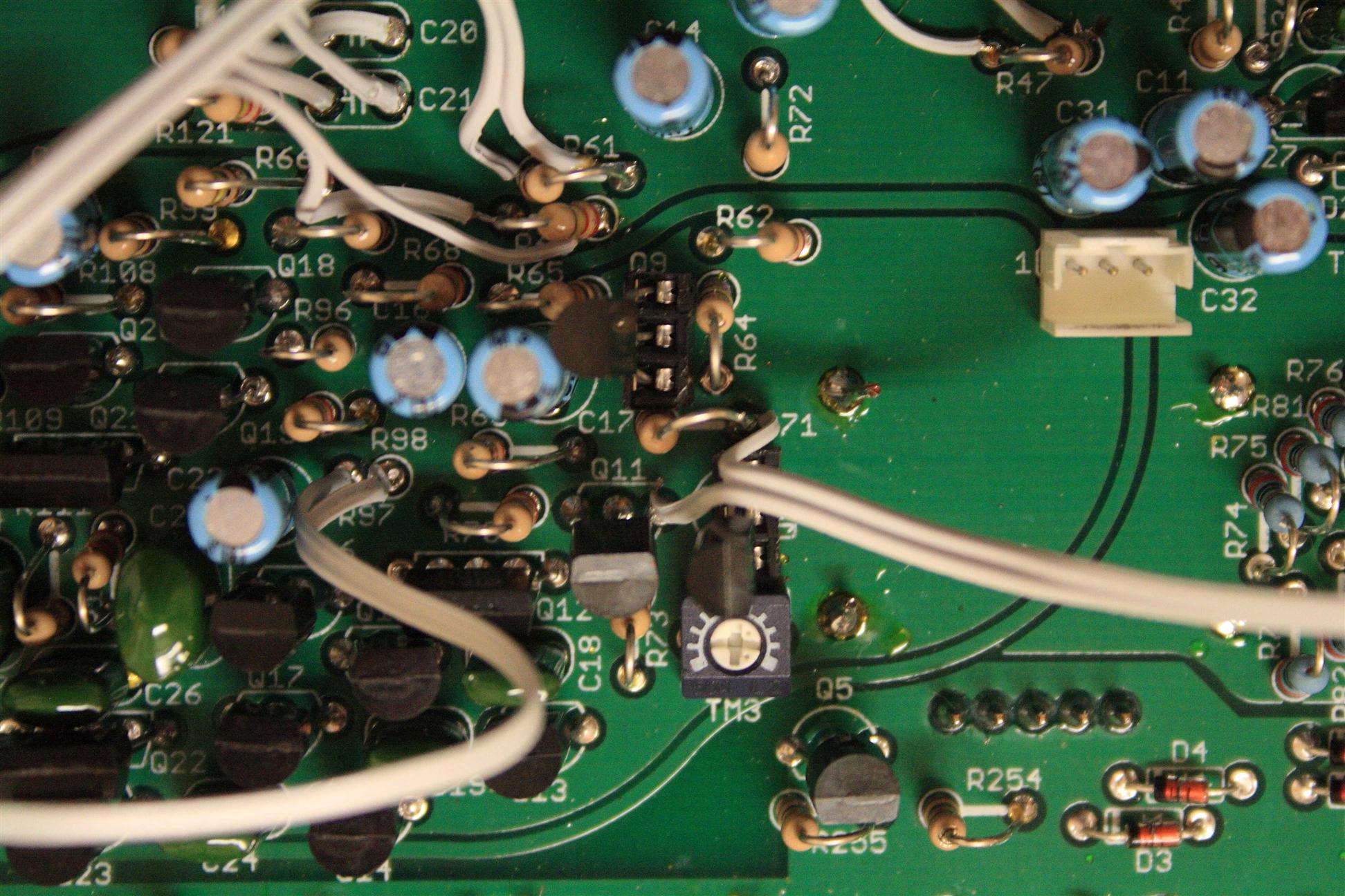
Devilfish Filter Overdrive
The DevilFish puts the filter into extreme duress. According to the engineer/artist you can overdrive the filter up to 66.6 times the original signal. R62 and C17 are responsible for attenuating the input into the VoltageControlledFilter from the VoltageControlledOscillator. If you don’t particularly care about the numerology or DevilFish purity, you can simply play with various resistor values until you find a sound that works. Conversely, you could mount a potentiometer instead. C17 might attenuate the signal too much, so you might need to replace it with a 10uF cap.Devilfish Like Overdrive
You could get a devilfish like overdrive if you remove R62,and put a 3.3K Ohm resistor in series with a 250K Ohm Pot.
Note that this does not let you turn the input all the way off like the devilfish.
----------
wire this in place of R62:
o 3
R62 / SW1 pin2 2 \
(in) From Switch ----o->/ 250k
\ C17(+) / R62
1 o-----/\/\/\----- (out)
3.3k
of course, that's a little inexact...
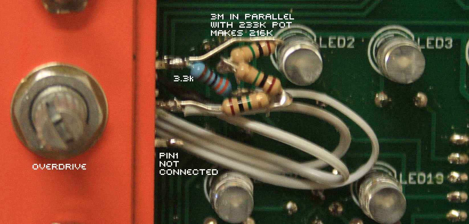
we'd rather go exactly from 220k (overdrive off) to 3.3k (devilfish mystical number)
o 3
R62 / SW1 pin2 2 \
(in) From Switch ----o---->/ 233k (actual value of my 250k pot)
| \
o/\/\/o-----------/\/\/\----- (out)
3M 1 3.3k C17(+) / R62
(in parallel
makes it a 216k pot)
---------- Parts List
simple option (won't turn all the way off):
- 250k pot (or 220k)
- 3.3k resistor
- optional: 3M resistor (or 3x 1M resistors)
Devilfish-like Filter Overdrive
Devilfish Overdrive Exactly
If you want to set up your overdrive like the devilfish so that it goes from all the way off to 66x over keep some things in mind. The VCO output is from 5.33v to ~10.5v, so you should make sure you reference Pin 3 of the pot to the 5.33V bias voltage. You can take this from many places, such as IC16 Pin7/IC16 Pin3/C60(+). Pin 2 of the pot is wired between the waveform swith pin 2 and R62. Pin 1 goes to a 3.3K resistor and then to the other side of R62/C17(+). A 100KA pot will do (but will color the sound, see below).
Connect in place of R62 resistor.

                          3 o---- 5.333V  (R101 or R36/J4 pin1)
                            /
                         2  \ 500kA
R62/waveformswitch pin2-o-->/
                            \      3.3K
                          1 o-----/\/\/\----- output to C17(+)/R62
Parts List
- 500kA pot
- 3.3k resistor
 100kA pin1 - R101 or R36/J4 pin1  (5.33V reference)
 100kA pin2 - R62/waveform switch pin2  (waveform pin2)
 100kA pin3 - 3.3k resistor - R62/C17(+) (output)
Beware! of the "overdrive exactly"...
-
(quoting bcbox from the forum)
"I found an intesting fact recently while continuing the design of a custom 303 mod. The output from the VCO is not buffered. In the stock 303 this is not a problem because the signal is just attenuated and then ac-coupled to the input of the VCF. However, if you add a level control that references to the 5.333v bias voltage of the 303 - such as you would if you were adding a level control - there is a load effect on the VCO signal if it is not buffered first. The result is that the character of the square wave changes quite significantly. It looks sublt on a scope but it is very audible. So you're better off not referencing your overdrive pot to the 5.333v bias point. I know that the devilfish doesn't buffer the output of the VCO so it would be interesting to compare the square wave coming from a devilfish with the overdrive/level control in place versus with it bypassed." http://www.ladyada.net/wiki/x0x/vcfmods#filter_overdrive . "The best thing to do is not to use a voltage divider but rather just current limit the signal into the VCF, simply use a 250k pot in series with a 3.3k resistor both in place of R62. This won’t allow you turn turn the VCO signal all the way off (short of adding a switch) but it’s not important for most people anyway"
Notes: only difference from the "devilfishlike overdrive" is the bigger 500k pot and connection of 5.333v to the pot's pin3.
Notes(2): I didn't like how this mod sounded. 1.) sound coloration 2.) even at "silence", I could still hear audible clicks. Because of this, the mod wasn't useful to me.
Notes(3): I reverted this change in favor of the "devilfishlike overdrive" current limiter version that preserves the default x0xb0x sound. I do not recommend using 5.33V here, unless you really need the silence (and don't mind some clicks instead of silence), or really want devilfish purity.
Notes(4): I didn't use a log pot, and it sounds fine.
Muffler like Distortion
The DevilFish has a post VCA soft-clip distortion called "The Muffler" that apparently retains bass response. Soft clip distortion is fairly easy to set up. You get a triple pole switch, and leave one of the poles disconnected, The other pole should lead to a diode going to ground. The other pole should lead to a pair of diodes going to ground, one of them reverse biased. The character of the distortion would change according to the diodes that you choose. You could change this circuit to double up on the diodes This also might make a passive filter due to C38.
From C38 ----+---- To VR8
             |
            /      SPDT on-off-on (intensity selection, low/off/high)
           o   o
 ~  ~  ~   |   |    ~  ~  ~  ~  ~  ~  ~  ~  ~  ~  ~  ~  ~  ~  ~  ~  ~  ~  ~  ~  ~  ~
           o   o
           |   +--+
           |      +--+--+
           |      |     |
           V      V     -  Diodes
           -      -     ^
           |      |     |
          ---    ---   ---
          GND    GND   GND


Here's a version with diode type selection:

 From C38 ----o---- To VR8
              |
             /   SPDT on-on     (diode type select, germanium/silicon)
(germanium) o   o (silicon)
 ~  ~  ~  ~ |   | ~  ~  ~  ~  ~  ~  ~  ~  ~  ~  ~  ~  ~  ~  ~  ~  ~  ~  ~  ~  ~  ~
            o   o
            |   |  DPDT on-off-on (distortion intensity, low/off/high)
           /    /
          o  o o  o--------------------+
 ~  ~  ~  |  | +--------------------.  |   ~  ~  ~  ~  ~  ~  ~  ~  ~  ~  ~  ~  ~  ~
    (low) o  o (high)         (low) o  o (high)
          |  |                      |  |
          |  +-----+                |  +-----+
          |  |     |                |  |     |
          V  V     -  Germanium     V  V     -  Silicon Diodes
          -  -     ^  Diodes        -  -     ^
          |  |     |                |  |     |
        ---  ---   ---            ---  ---   ---
        GND  GND   GND            GND  GND   GND
Choosing Diodes
From the Guitar Effects FAQ:
Silicon is reputed to clip abruptly, causing a harsh sound. Germanium clips at about half the voltage of a silicon diode, but is reputed to turn on more slowly in its smaller range. LEDs turn on at about two silicon diode drops, and are also reputed to be slower turn on, with it and germanium giving more “tube like” sounds. Some units with “tube” in the title use LEDs or germanium for clipping. Oddly enough, the Marshall JCM800 uses a set of two pairs of silicon diodes back to back as clippers. This seems strange in a Marshall, but it is there. When I looked at the schematic, I first thought it was a protective clamp for a tube grid, but the circuit doesn’t work that way. They are there for the distortion.
Parts List
- 3 LEDs
- 3 germainium diodes
- 3 normal diodes
- SPDT on-on switch (3 legs) - select diode type (type of distortion)
- DPDT off-on-on switch (6 legs) - select number of diodes (intensity)
  VR8/C38 - SPDT input pin2
  SPDT pin1 - DPDT input 1
  SPDT pin3 - DPDT input 3
  DPDT pin1a - 1 LED in
  DPDT pin1b - 1 germainium in
  DPDT pin3a - 2 LEDs in
  DPDT pin3b - 2 germainiums in
  LED/Germainium outputs - ground (VR8 body)
Notes: this mod seems to be a suggestion, not an authentic devilfish mod
.JPG)
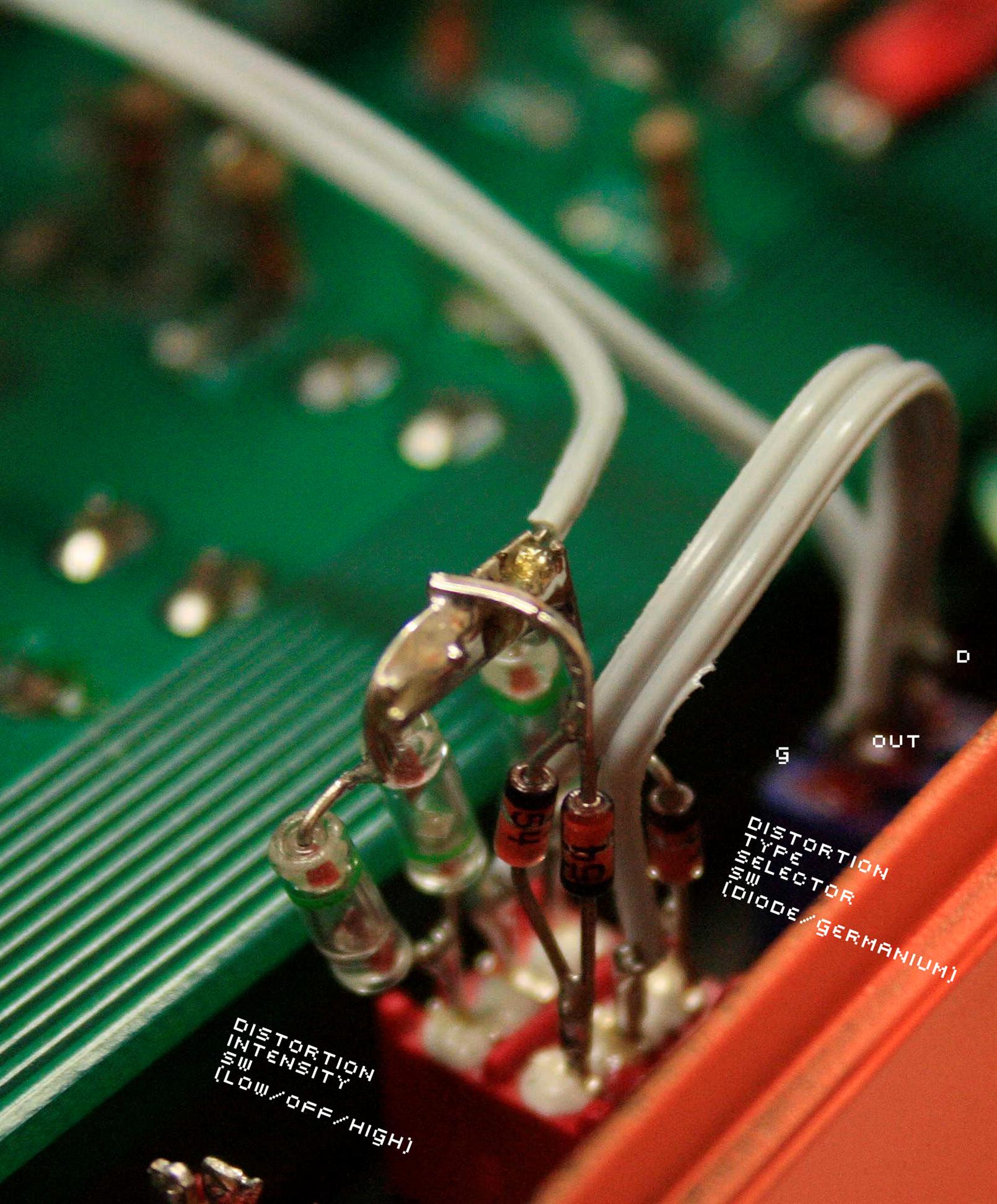
Muffler-like distortion