MintyMic - a DIY powered stereo microphone + preamp with line-level outputs and adjustable gain control
   |
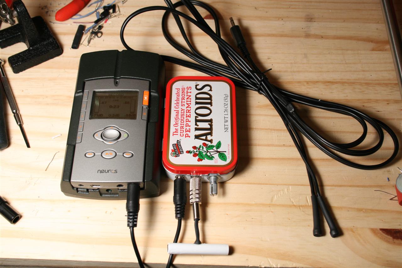
This is a high quality, yet inexpensive, stereo microphone suitable for line-in level inputs... It is based on 2 Panasonic WM-61a electret microphone capsules (about $1.80ea at digikey), a preamp circuit running off of a 9V battery all packed into an Altoids tin. When powered, it supports very high SPL and can record quiet ambient sounds as well as loud concerts. The whole kit can be built for as low as $30 in parts. Compare this to professional models at $200 or higher... The microphone is simple, just solder on some capsules to the ends of 1/8" minijack cabling and secure with hotglue and heatshrink. It's expected that 9V is applied across the microphone capsules, which help them handle higher SPLs, and the preamp provides this voltage at the input. The preamp supports 3 different gain levels, 2x, 23x, and 72x, and has an attenutation (volume) knob at the output of the circuit. The preamp also supports 2 types of electret microphone, standard, and "modded" - which is the wm-61a's FET wired up in "source follower" mode (some call this the "linkwitz mod"). The preamp runs off a 9V battery, and has an on/off switch. For size, stealth, and plain "cool factor" i've housed all this into an Altoids tin. I also have a (as yet untested) PCB layout design below, which should make building this unit very easy. My 1st prototype was built on protoboard (see pictures below).
Features
|
worklog
Saturday 04.29.2007
10pm - 12pm I've been studying a few designs for building a DIY mic with line level output. I've decided to use the Panasonic WM-61a. People have reported high quality results with this setup for recording really loud things (concerts) as well as quiet ambient sound.
Each mic is only $1.80 + cables/heatshrink for around $5.
To get the higher quality, the mics must be powered to handle the higher SPLs. The power circuit contains 2 resistors (10k), 2 capacitors (2.2uF) - one at each output, and a battery (9V), cheap!
In addition to powering the mic, I also want a preamp to boost the output for quiet recordings (i.e. ambient sounds). For a line level input, only loud concerts would drive the line input loud enough for a good recording. So we need amplification. The preamp circuit contains a lot more parts than above and costs a little more (maybe $15). It's standard non-inverting opamp stuff: gain (rf/ri + 1), midrail voltage, caps to prevent DC flow at input and out, with electret mic power factored in as well.
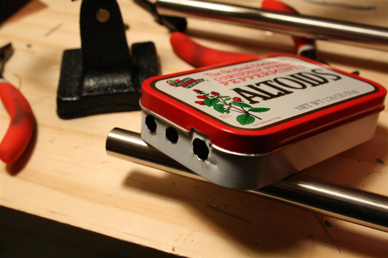
I plan to build the preamp/powersource into an Altoids box, it's small, compact, very cheap as project-boxes go, and provides nice shielding for the circuit. :)
Something Tricky: I'd also like to do the "source follower" modification to the electret capsules (see WM-61a pictures below), which is a modification of the microphone capsule which allows them to handle even higher SPLs as well as have less distortion. The electret is a FET (field effect transistor), and this modification changes the wiring of that FET to be a source follower.
power supplies for different WM-61a electret microphone types:
a.) standard, and b.) modified (source follower)
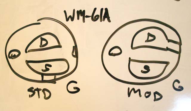
how to modify the Panasonic WM-61a to handle higher SPLs
cut a trace, solder a connection, done!
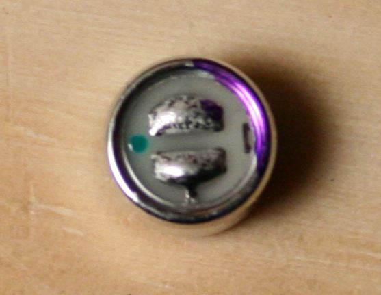
here's the unmodified mic...
Tuesday 05.02.2007
10pm - 12pm For kicks, I want the preamp to be compatible with both modded and standard unmodded microphones, so tonight, I diagramed a simple low-cost switch for this (i.e. you'd need to open the altoids lid to change 4 jumpers). This "switch" can be a simple 8 pin DIP socket with insulated wire jumpers either going 1.) straight across (standard) or 2.) in X's (modded) - see the picture below.
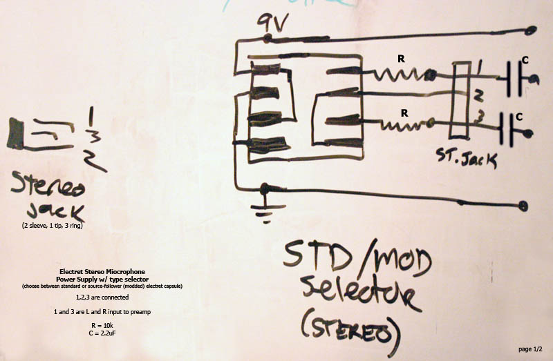

electret stereo microphone power supply w/ type selector
(select between standard and source follower (modified) types)
(designed for Panasonic WM-61a capsules)
Saturday 05.05.2007
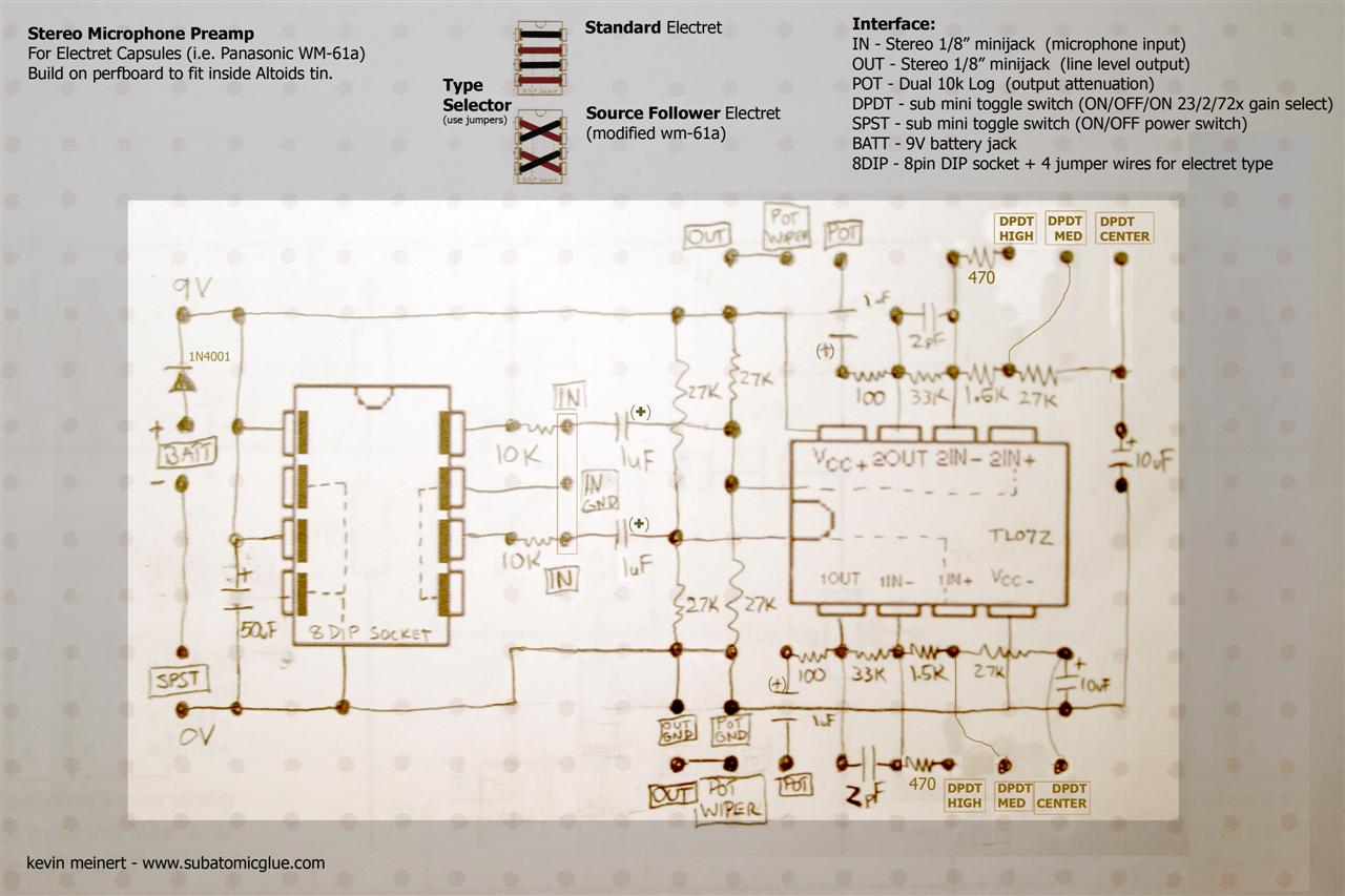
8pm - 11:30pm Created a rough "first pass" schematic for the preamp prototype. The design is standard non-inverting opamp stuff: gain determined by rf/ri + 1, midrail voltage bias at opamp input (because the signal swings + and - this reference point), caps at circuit ins/outs to isolate DC from the outside (only recieve/transmit AC signals), caps (10uF) to reduce DC opamp gain (we only care about amplifying AC signals), diode to enforce battery polarity, with electret mic power factored in for both types of electret (standard and modified). I got a lot of inspiration from this page. Read it, understand it, you'll learn a lot.
This layout should transfer to PCB well... the design here is intended for perfboard (i.e. from Futurlec), which, when cut down, should fit inside an Altoids tin, not a lot of space to spare!
 -->
-->

electret stereo microphone preamp w/ type selector
(select between standard and source follower (modified) types)
Microphone Preamp Bill of Materials (prototype)

1x  9V battery
1x  9V battery connector
1x  Altoids tin
1x  Perfboard
1x  1/8" stereo jack in
1x  1/8" stereo jack out
1x  SPST switch (power on/off)
1x  DPDT switch (gain 2 or 23, or 72)
1x  50uF polar radial (i.e. 47uF)
1x  10k log pot (dual)
1x  TL072 opamp (or NE5532)
1x  1N4001 DIODE (protect opamp from reversed battery)...
4x  1uF polyester film (i/o)   (or 2.2uF polar radial)
2x  10uF polar radial
2x  100 ohm
2x  470 ohm
2x  33k
2x  1.5k
6x  27k
2x  10k
2x  2pF  (opamp stability - 1pf used here)
Wednesday 05.09.2007
8pm - 9:00pm parts for the prototype arrived! I separated them into 3 "kits", it was all pretty cheap, about $70 total... ($14 of that was shipping, bah!)
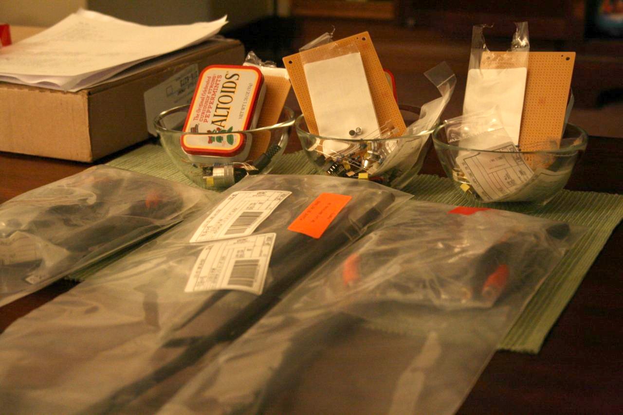
3 microphone kits waiting to be built

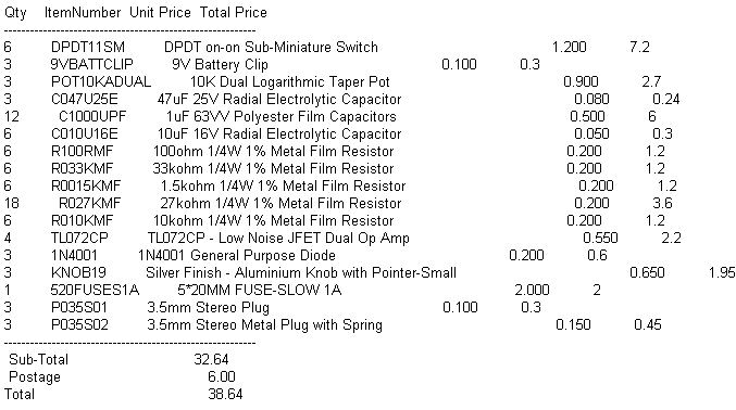
order invoices from digikey and futurlec
Sunday 05.13.2007 - Thursday 05.17.2007
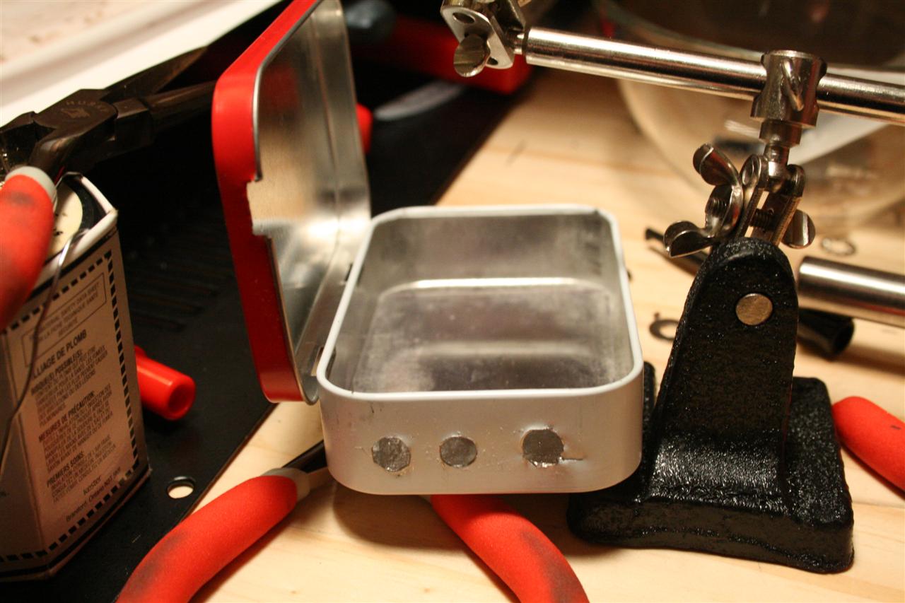
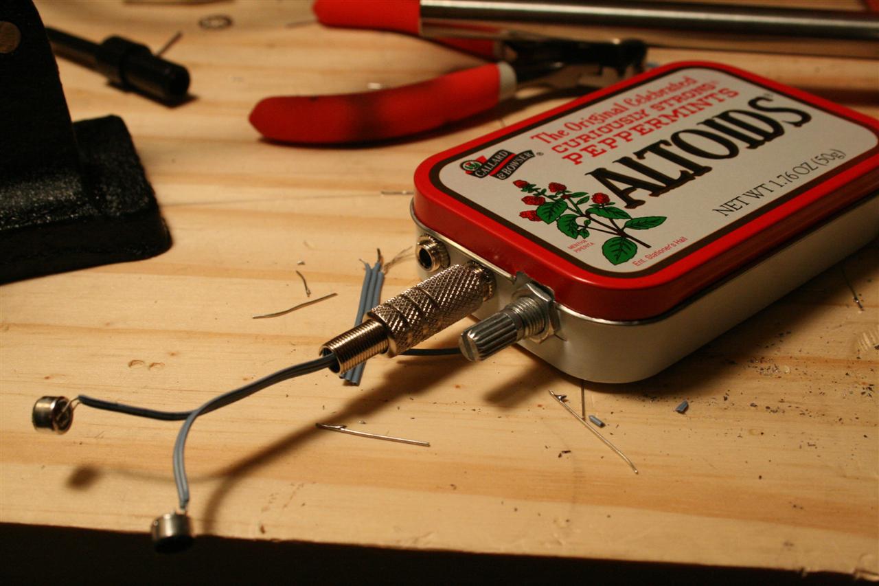
9pm - 12pm (3 nights this week), spent a few nights this week assembling the PCB and drilling the altoids tin. The Altoids tin was very thin and easy to tear with the drill. It took a long time to wire up the back of the PCB, but you can see it's mostly a pretty neat job. For soldering, I started at the I/O jacks and worked my way down towards the 9V battery.
I tested this with headphones plugged into the line out. Sounds good.

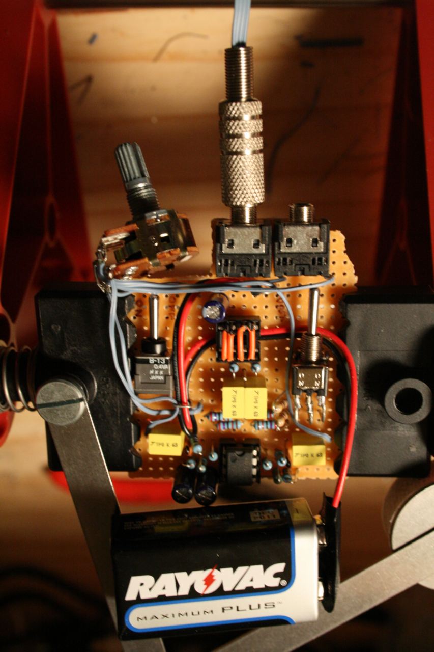
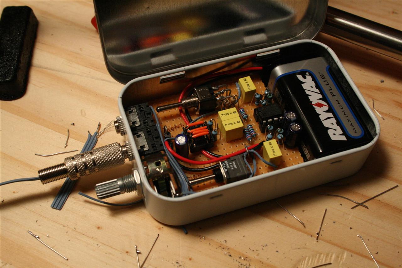
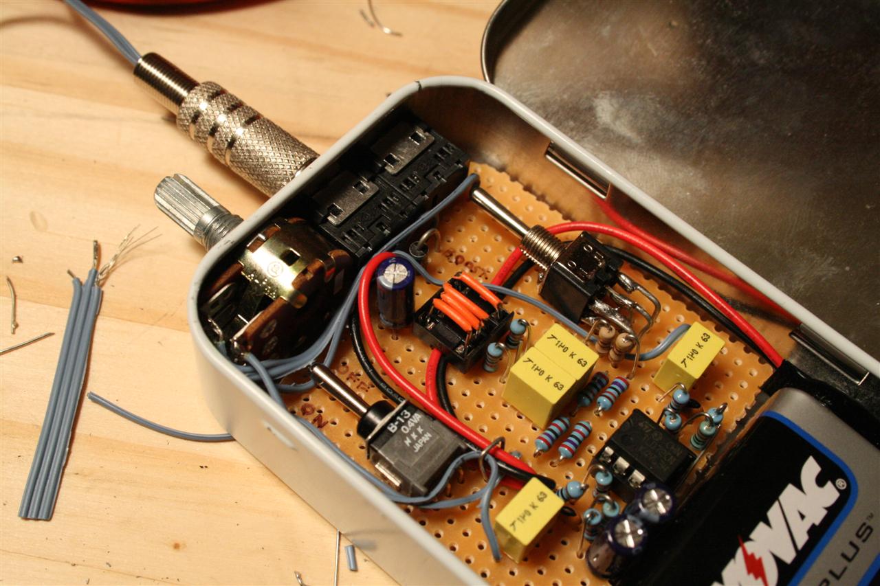
building the prototype microphone and preamp
built a quick microphone for testing purposes
Friday 05.18.2007
10pm - 12pm I did my first test with the mp3 recorder and the new Microphone+Preamp. I found some bugs, so tonight, I fixed 2 problems and (bonus) added a feature:
Problem 1.) up until now, I had been testing the preamp with headphones connected to the line out. Tonight, when I plugged the preamp into my mp3 recorder's input for the first time, I heard a swishy noisy sound with the high-gain boost turned on. As it turns out, the opamp was self oscillating (in an unstable condition due to high gain). Besides being "swishy" and noisy, the sound of the microphone was also very degraded - the self oscillation was likely well above 20khz (upper hearing limit for humans) with large and clipping amplitudes affecting the amplified signal from the mic. I fixed this problem by adding a 1pF cap to each opamp across the 33k resistor, which creates a low pass filter. (At high frequencies the capacitor acts as a short, so the gain of the amplifier goes to zero.)
Problem 2.) I had the gain booster switch shorting out the 100ohm resistor instead of the 27k. Oops. So, instead of changing the gain (ratio of resistance in feedback vs. input to the opamp) I was changing attenuation (signal strength at opamp's output). Boost is better now, but ... now I think I want more... boost! (see next item :) )
Feature !.) added a 2nd gain setting - 72x gain! woo. I can hear my fingers rubbing gently together a meter away from the mic. I just used the 2nd "on" setting in the boost's on-off-on DPDT switch.
Saturday 05.19.2007
11pm - 4:00pm took the new mic to maker's faire... recorded some exploding flamethrower things...
 boom15.mp3 ch2.mp3 boom15.mp3 ch2.mp3 |
noise2.mp3 shhh3.mp3 |
flamethrower-song.mp3
yes, I made a little song out of my flamethrower samples
Thursday 05.24.2007
11pm - 3:30am Created PCB design and schematic. I also changed the 4-jumper "switch" to a 3-jumper switch. yay, less parts. This design relys on a header and some jumpers - rather than the simple 8 pin dip socket. cleaner design, hopefully just as cheap...
Update: Added optional switch for the type selector, and optional LED...


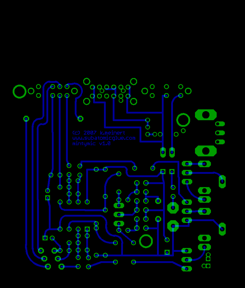
Schematic and single-sided PCB layout (2.5 x 2.15 inches @ 300dpi)
MintyMic - Microphone Preamp Bill of Materials (final v1.0)

1x          9V battery
1x  G1      9V battery connector
1x          Altoids tin
1x          PCB (or Perfboard)
1x  J2      1/8" stereo jack in   (cui SJ-3544 1/8" stereo jack at digikey)
1x  J4      1/8" stereo jack out   (cui SJ-3544 1/8" stereo jack at digikey)
1x  SW2     SPST switch (power on/off)
            (ESWITCH EG2215 DPDT on-on right angle switch at digikey)

1x  SW3     DPDT switch (gain 2 or 23, or 72)
            (ESWITCH EG2315 DP3T on-on-on right angle switch at digikey)

1x  C2      50uF polar radial (i.e. 47uF)
1x  V3/V4   10k log pot (dual ganged - Alpha 16mm-base 'mini pot')
1x  IC1     TL072 opamp (or NE5532)
1x  IC1     8-pin DIP socket   (optional - for opamp)
1x  D1      1N4001 DIODE (protect opamp from reversed battery)...
4x  C5/C52, 1uF polyester film (i/o)  (16v)
    C6/C62

2x  C3/C32  10uF polar radial  (16v)
2x  R1/R12  100 ohm
2x  R5/R52  470 ohm
2x  R2/R22  33k
2x  R3/R32  1.5k
6x  R7/R72, 27k
    R8/R82,
    R4/R42

2x  R6/R62  10k
2x  C1/C12  2pF  (opamp stability)
1x  JP1     12-pin DIP male header block  (optional)
            (male - 2 rows of 6 - 0.1" spacing, 0.025" posts)
            (for electret type selector - optional - can use jumper wire instead)

3x  JP1     jumper wire or shorting jumpers (optional instead of switch)
1x  SW1     4PDT switch (optional - instead of header/jumpers)
            (E-Switch EG4208 4PDT on-on right angle switch)

1x  led     LED (optional)
1x  res     LED resistor (optional - experiment to see what works
                             make the LED dim to save battery!)

20x JP2..9  jumper wires (any small cut lengths of wire)
    VR3-POTA,
    VR4-POTB,
    SW1-JP1,  (optional typeselector switch))
    J2A-J2B,
    led-led   (optional led)
Sunday 05.27.2007
4-5pm, 8-9pm Today I created a long (2 meter) stereo microphone, this one with the sourcefollower modification. It's amazing how simple this is to make, yet it costs $70 - $100 at some online stores.
I also finished off my short test microphone (pictured above). I used a pen cap and some heat shrink tubing to reinforce the structure to keep the wire from bending too much. This is a really easy microphone to use, easy to build, and about $7 to build - I've seen this style of mic sold for $70 at some online stores...
First, I set the jumpers inside the preamp box to "modified" (the XX configuration pictured in an above diagram), and when I hooked it up, I heard nothing, and the diode got really hot... oops... turns out that I didn't realize that the Stereo IN and OUT sleeves both must be isolated from each other, because in MOD mode they are at different voltages. In STD mode, they're both 0V, but in MOD mode the IN jack is 9V while the OUT jack is 0V. The Altoids tin is metal!!! (it's a great conductor). Which since the sleeve part of both jacks touch the tin, they make contact, and we're seemingly screwed. But... all is not lost. For the IN jack: I made the Altoids hole bigger, isolated both sides with plastic, and wrapped the sleeve part of the jack with a thin band of heat tubing. It works! So now both types of microphone work - I can flip a jumper inside to support either style... The source follower microphone is slightly quieter than the standard type. I'll do a concert-level test later.

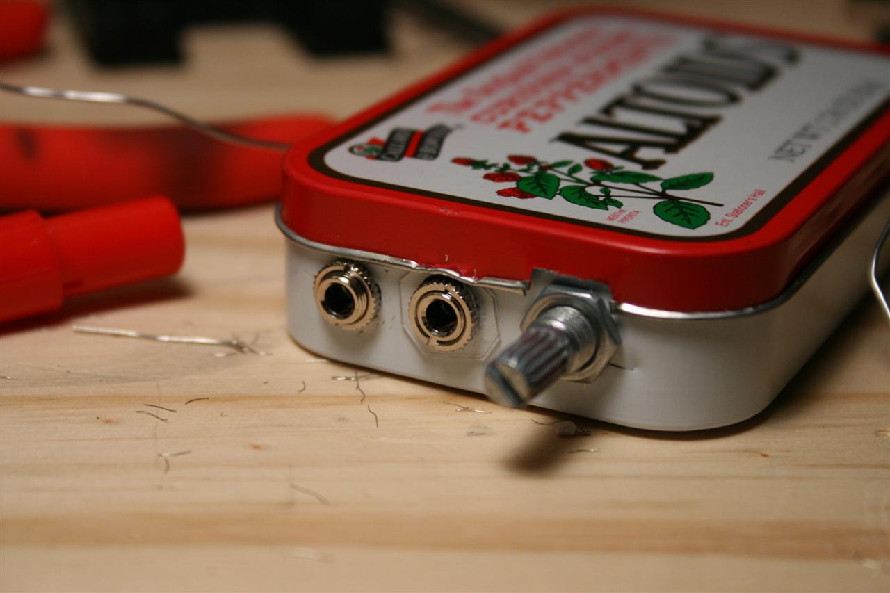
Using source follower type microphone, see jumpers.
Must isolate the INPUT jack from the case (because OUTPUT is always at 0V)
INPUT sleeve could be at 9V or at 0V depending on the microphone type used.
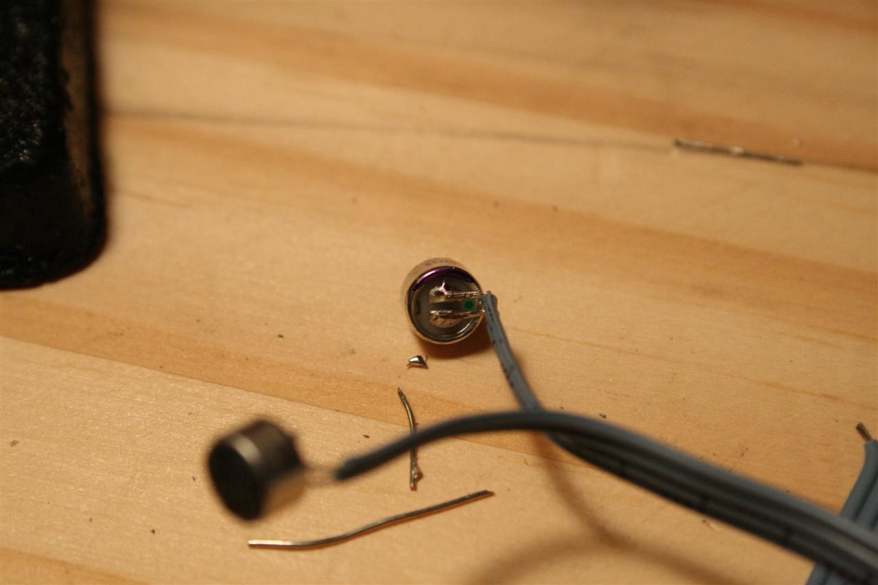
Modifying the microphones is tedious, since they're very small. The key is to rough up the metal near the drain pad so the solder sticks when we bridge the pad to the casing. There's a little piece that sticks out under the lip of the capsule body that is crome with copper underneath, just scrape off the chrome, and rough up the metal lip too (more surface to stick to can't hurt)... Fine tip solder iron helped here, the screwdriver tip was pretty big and awkward.
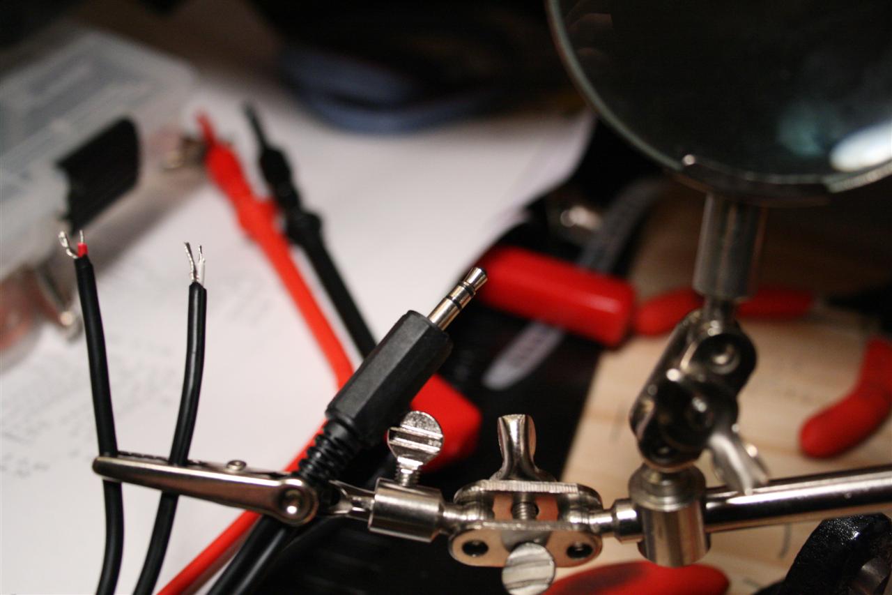
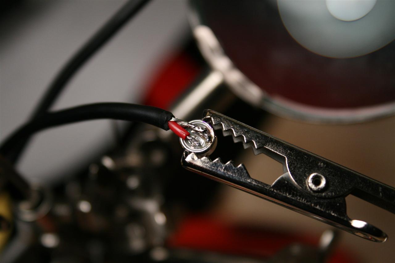
getting ready to solder the mic cable
1.) Original microphone. 2.) Microphone with source follower modification
Notice the cut trace on the bottom pad, and the top pad now connected to the case.
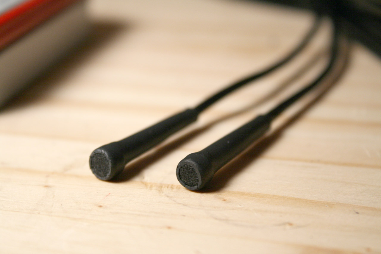


2 finished microphones
1.) 2 meter long stereo mic, for easy placement and "stealth recording" (modified electret)
2.) Stub mic for convenience and to minimize wires (standard electret)
Conclusion
So this project was pretty easy to get running quick, about 4 nights - lots of labor soldering and fitting the prototype altoids box, and maybe 5 nights on PCB design since then. And the mic sounds good! The price was not bad too, the prototype MintyMic was under $30 for two microphones + preamp. Compare this to $229 for comparable models (preamp + stereo mic) sold online, and I have a huge win for myself here. :) I also have the possibility of selling kits - since I have a PCB design and parts list, and I may make a run of them if people are interested... contact me and I'll add your name to the waiting list.
The biggest surprise designwise was when using the modded microphone, I hadn't factored in the metal case connecting the two jacks, which when switched to "modded mode" one jack is at 0V and the other at 9V - essentially shorting out the 9V battery (made the 1N4001 diode pretty hot too). Kind of a newb mistake, but it was easy enough to figure out and solve, and now the case truely works for both kinds of microphones (and sounds good too).
I intend to use this to record strange sounds for samples to be used in music. I've typically done this for percussion and ambient sounds in the past, but really anythings possible. :) I've already created the flamethrower-song, and this was just a small taste of what's possible with only 10min of work chopping up wavs and arranging into a track...

done... I now have a portable stereo recording studio with 2 microphone styles.
Future Work
cut power when input is unplugged
find an easier method to keep input jack from touching metal case (nylon washers+ heatshrink?)
(only matters if using modded microphone)
test source follower mic with loud sounds, compare distortion levels with standard mic. (low priority, but might be interesting)
print up some PCBs, make mintymic #2...
find a suitable (small enough) PCB mount dual-gang pot
add a DC power jack? maybe...
links
- greenmachine's DIY microphone and batterybox project
- Simple Stereo Electret Microphone Preamplifier
- linkwitz labs - electret source follower mod
- another nice diy project for wm-61a - some nice pictures of mic mod