9090 worklog
|
I built the 9090 analog drum synthesizer. A "9090" is a clone of the classic Roland TR-909 drum synthesizer. On these pages is a worklog created as I built the synth. Jump ahead to the:
Listen to the finished 9090: |
Monday 04.03.2006
6pm came home today to find the 9090 PCBs from Trevor came through my mail slot. 2 PCBs and 4 ICs.
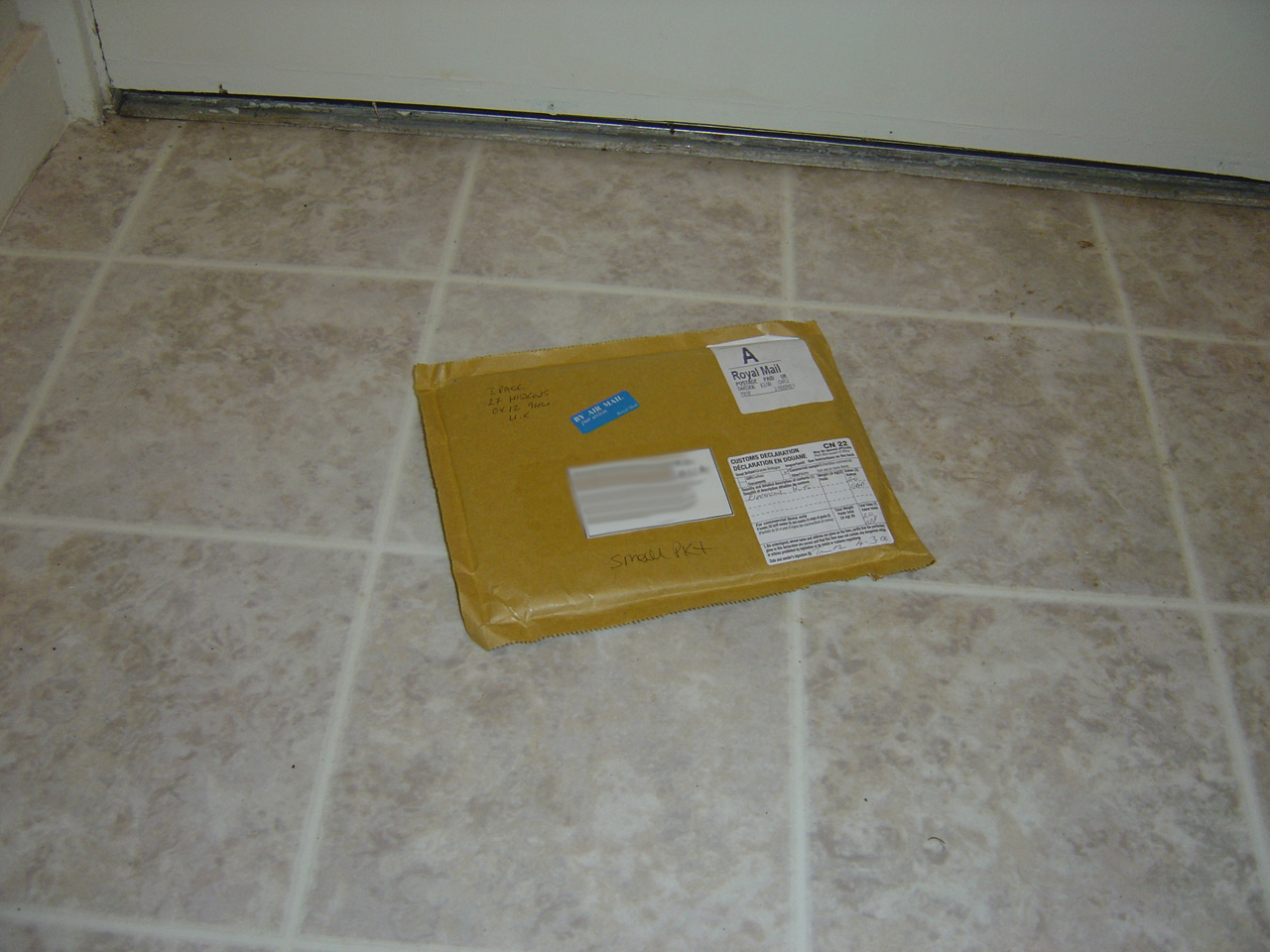
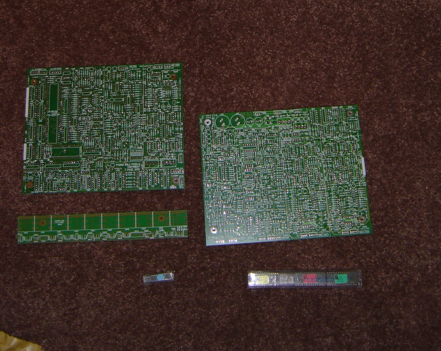
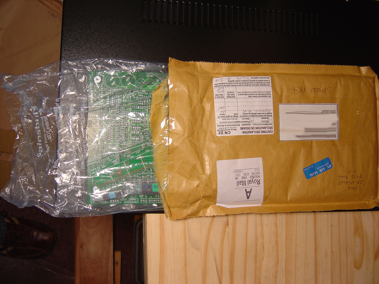
9090 boards from trevor arrived
I found some nice scans of the PCBs on c0nsumer's 9090 wiki.
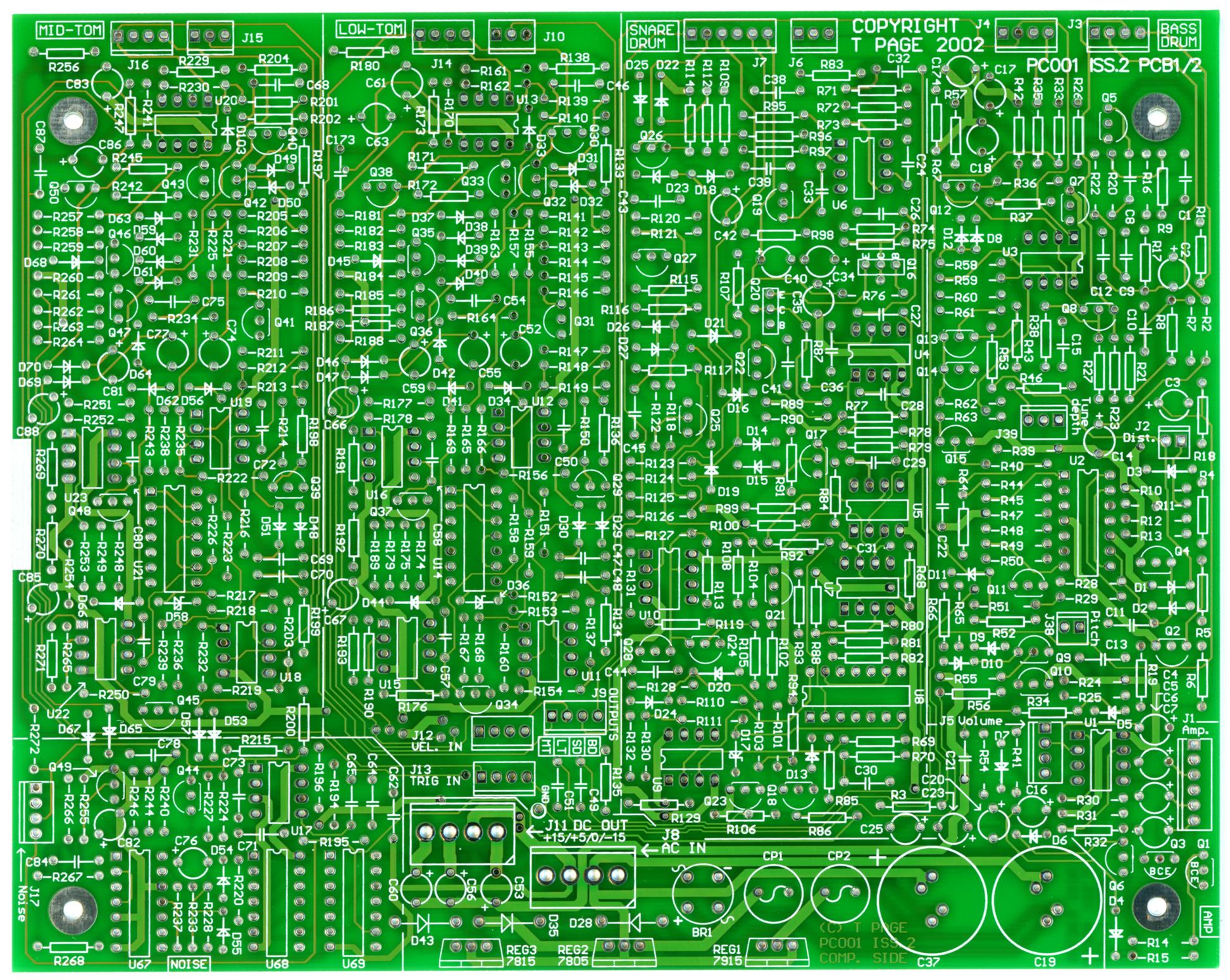
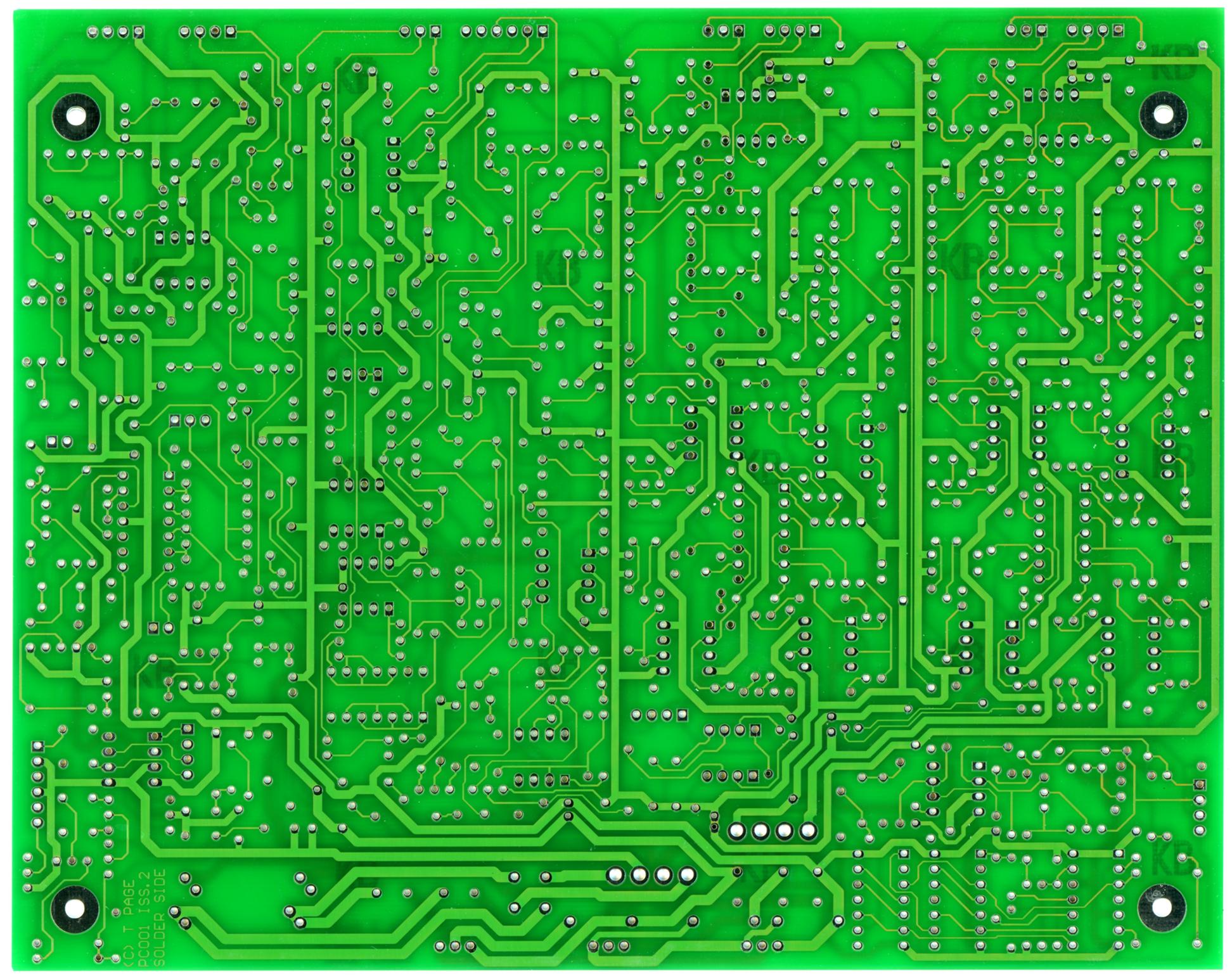
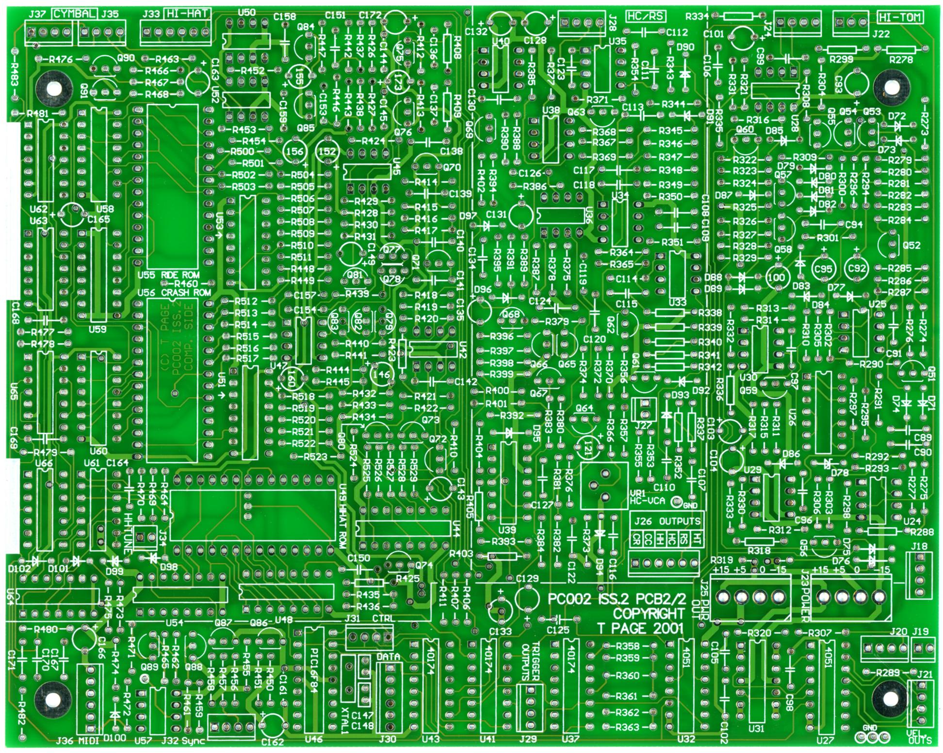
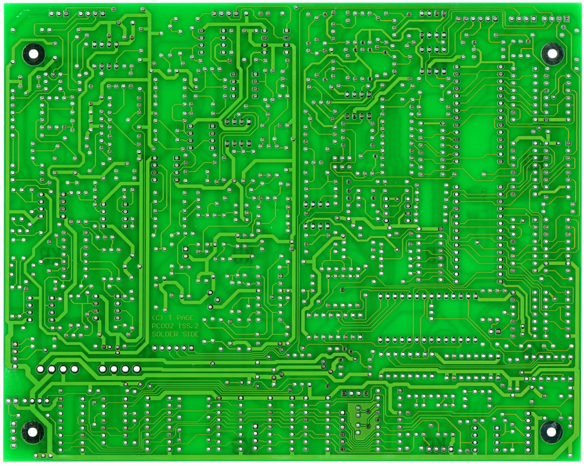
![]()
![]()
PCB scans
Tuesday 05.09.2006
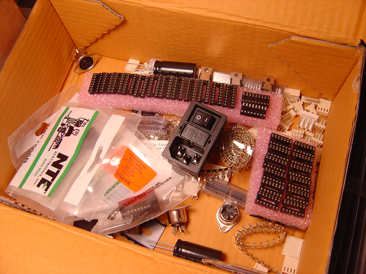
6pm Recieved group order of original 909 parts from marco. These should substitute for a few of the modern parts in Trevor's BOM... making the 9090 closer to the stock parts listed in the original Roland TR-909.
Parts from the group order...
909      |  9090
----------------------------------
M5218A   == TL072   opamp
2SC2603F == BC549   npn transistor
2SA1115F == BC559   pnp transistor
2SA798   == BC559   pnp matched pair (Q65-66, 80-73, 77-78, 79-82)
1SS133   == 1N4148  diode
            CA3080
            D1469SD
            2SC2878
Sunday 06.04.2006
6-12pm Created a sortable/collapsable parts list (bill of materials) based on Trevor's 'official' 9090 parts list. The 9090 parts list is organized by section, so isn't very easy to get a unique count of every part type. This makes it harder to make an order (i.e. from mouser/digikey), since you'd have the same part in multiple sections (redundancy)... To get organized, and to also create partslist that might help people source parts easier/faster, I compiled the list into an Excel doc with macros for sorting the components (see the buttons at the top of the page).
sdclements and I worked on this, and also added links to mouser/digikey/futurlec in the doc. should be current for at least a month or so :) after that, it should give you a good idea where these parts can be obtained, in most cases if the part doesn't come up, you can just search for it and find an alternate...
Download:

9090_partslist_ver1.0.6-subatomic.xls
UPDATE 06.23.2007 I found several inaccurate quantities in the 9090 parts list from 5/Jan/04, excel sheet has been updated.
Monday 09.04 - 09.08.2006
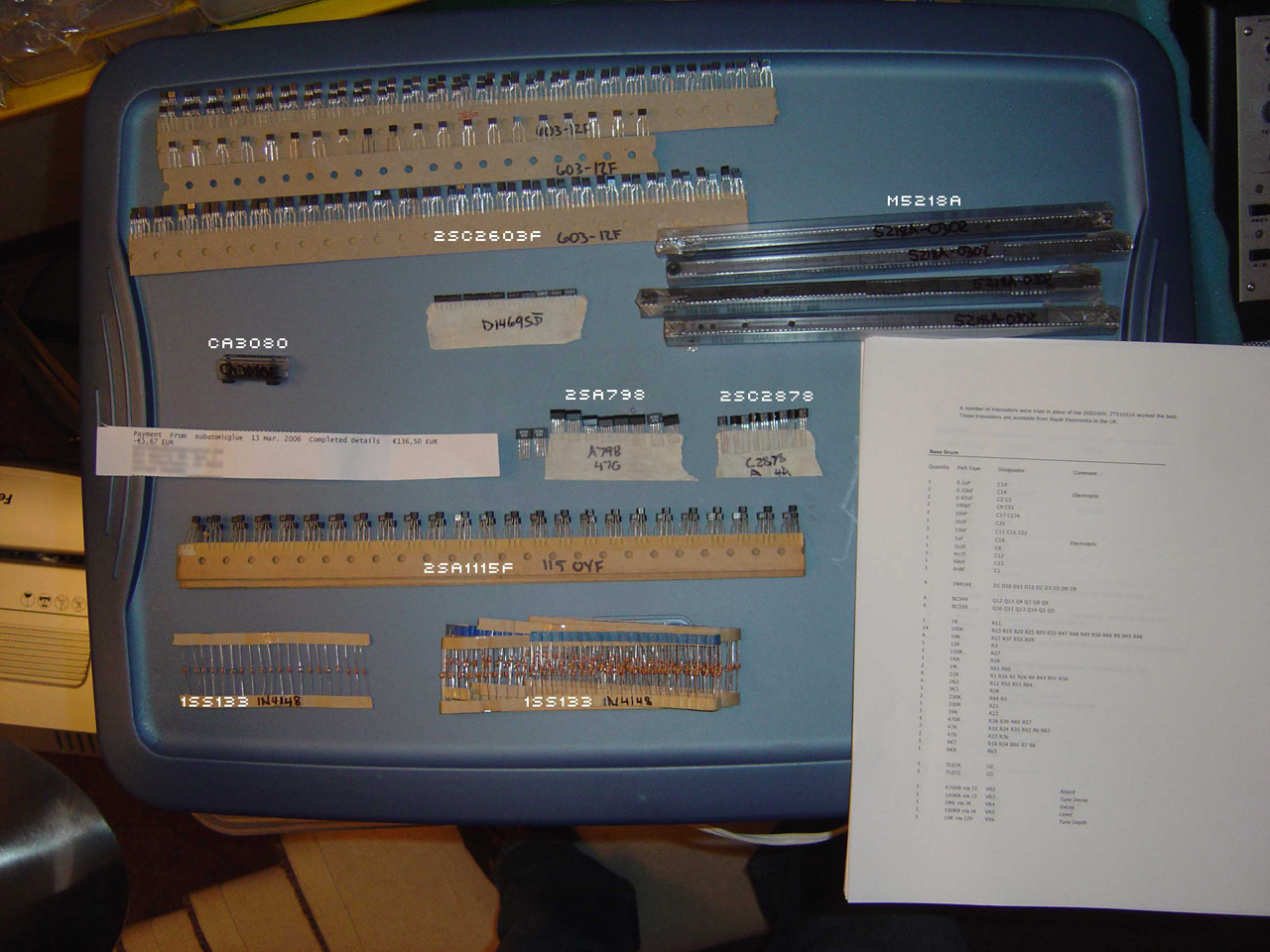
6pm Put together a group order for the remaining parts for the 9090. I'm putting this together for sdclements, ceedub, and myself... This took forever, probably because I taped every part to 8.5x11 paper and double checked that we got what we needed.
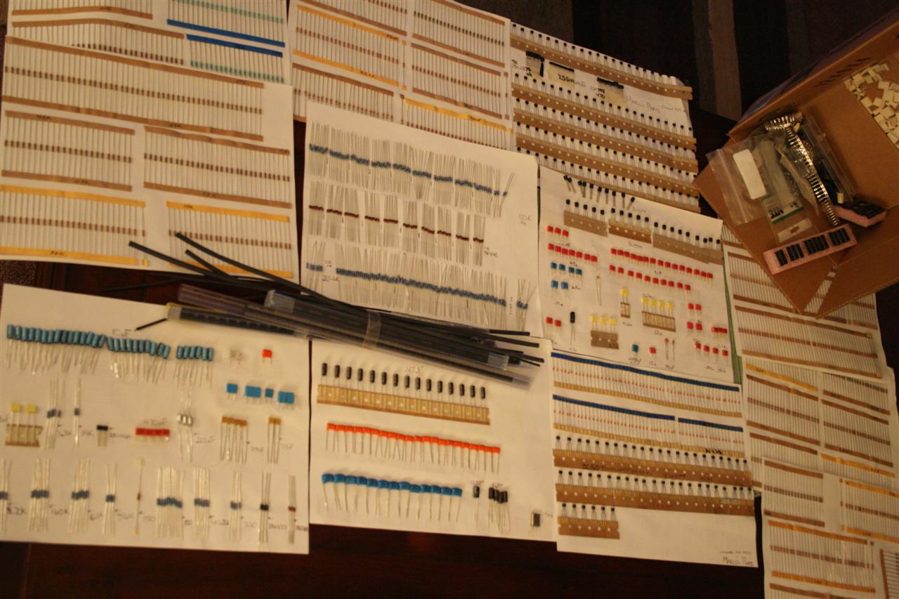
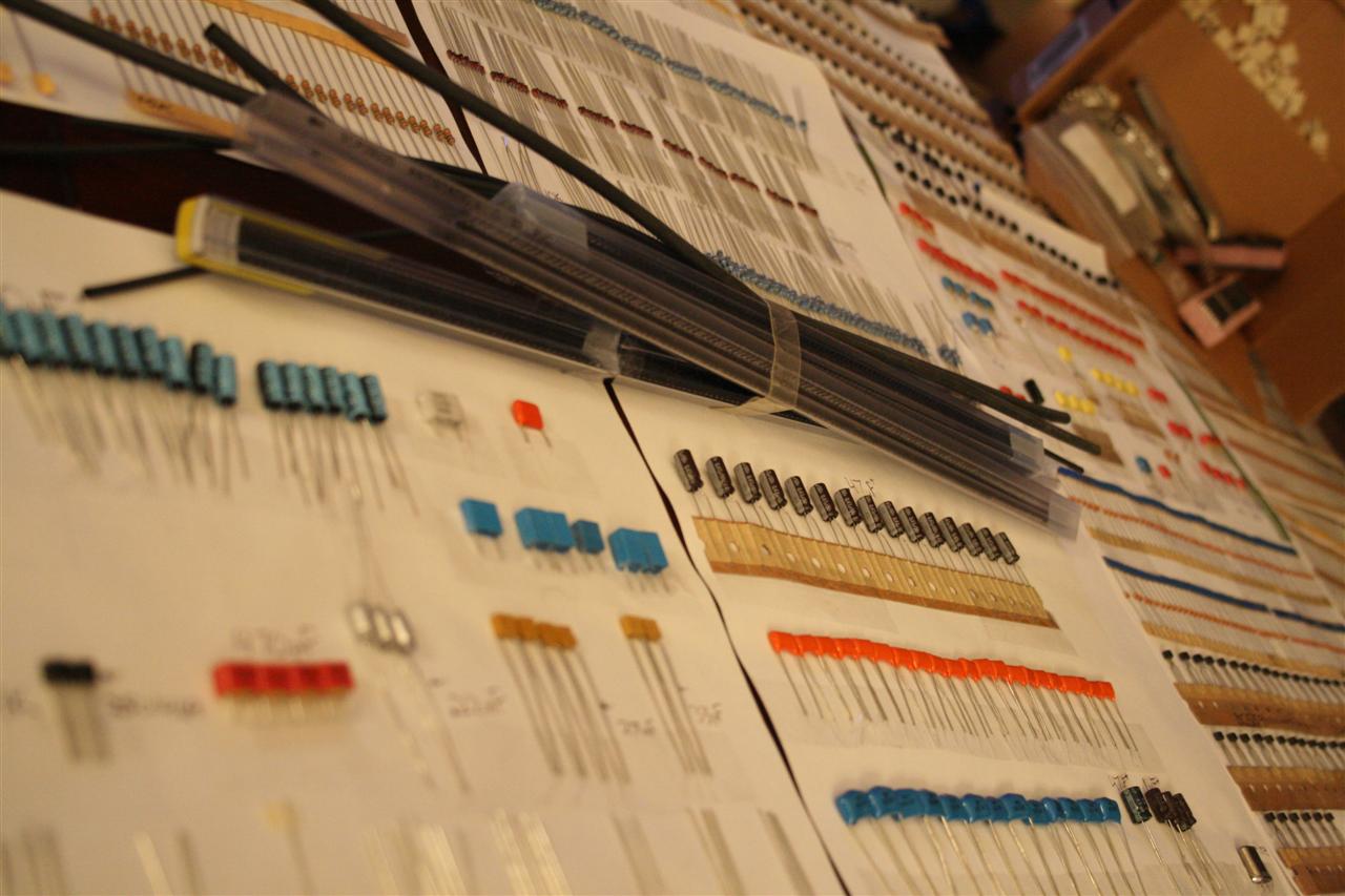
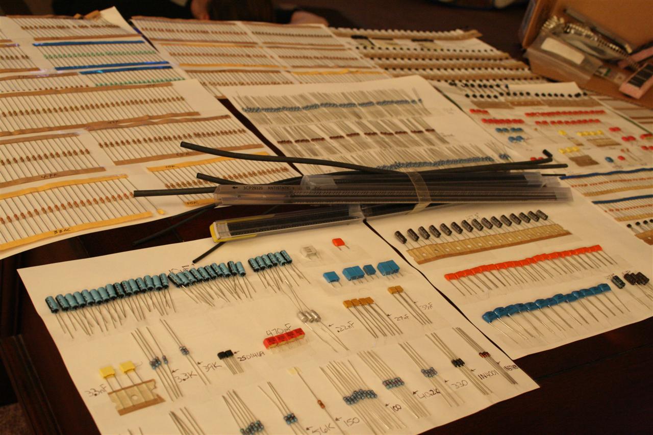
this is just one set of parts for building a 9090
(not including the case, knobs, pots, transformer, 1/4" jacks)
Friday 09.15.2006
12noon Sent out the 9090 parts to ceedub and sdclements... Glad to be done with this. Sourcing parts is tedious, and takes a lot of time.
Friday 01.26.2007
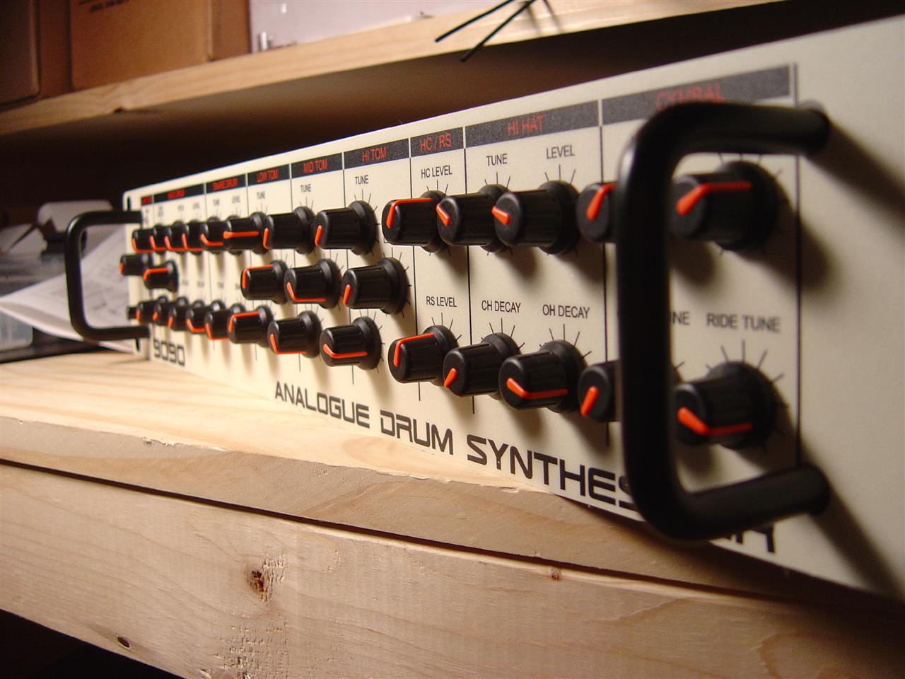
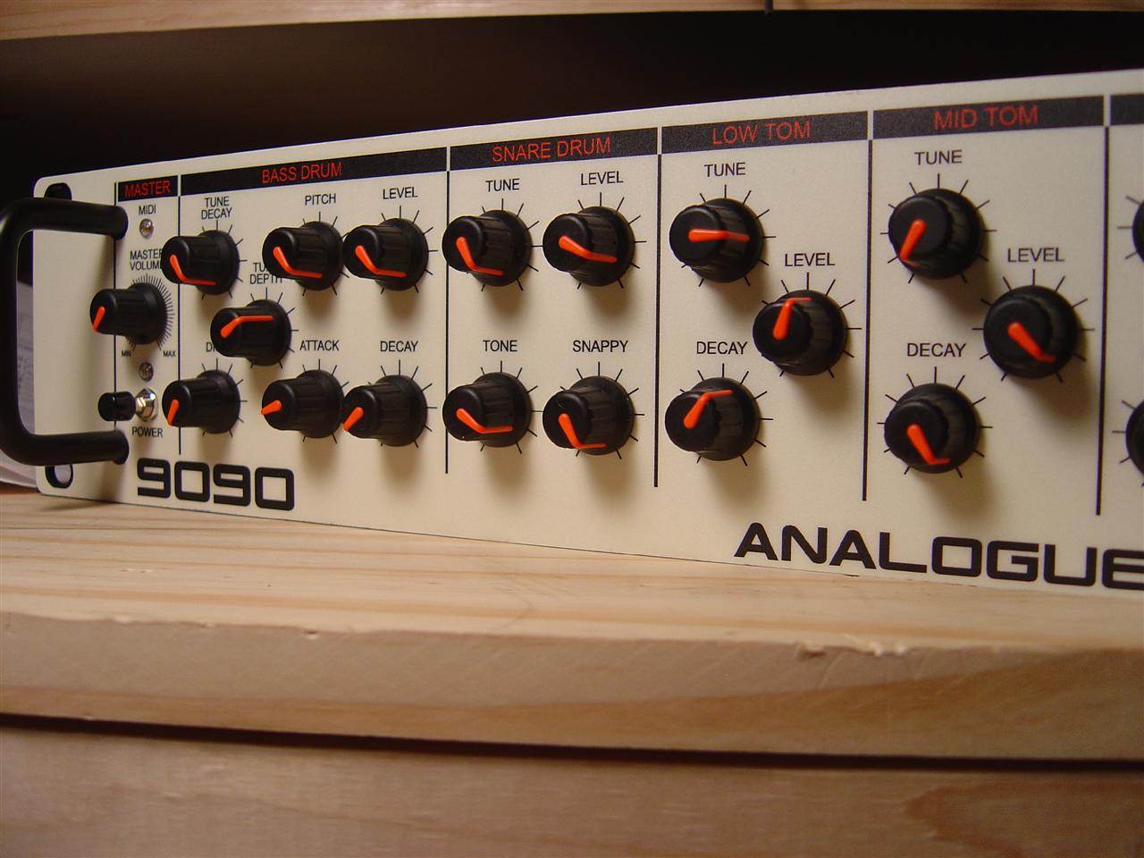
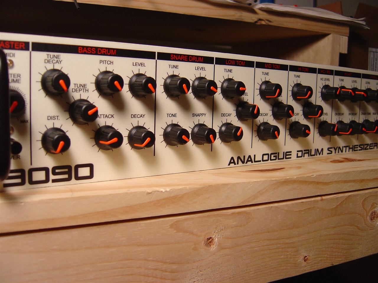
8:00pm Recieved my 9090 case in the mail from Steve on the 9090 list. Great work, see the pictures. He did all the drilling and designed the front panel graphic. For whatever it's worth, I got case #1 in the run of 20. The case is an "E STAR Technology Co., LTD. 19" Professional Rack, model ET2/30B. The screws holding it together seem a little cheap, but the panel looks great, and all together I think it will be sturdy enough.
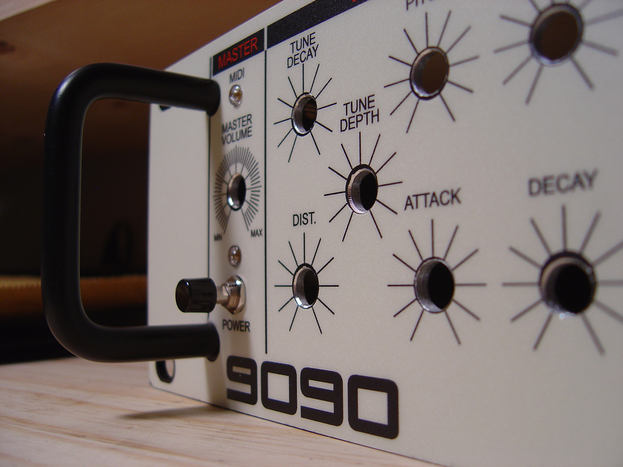
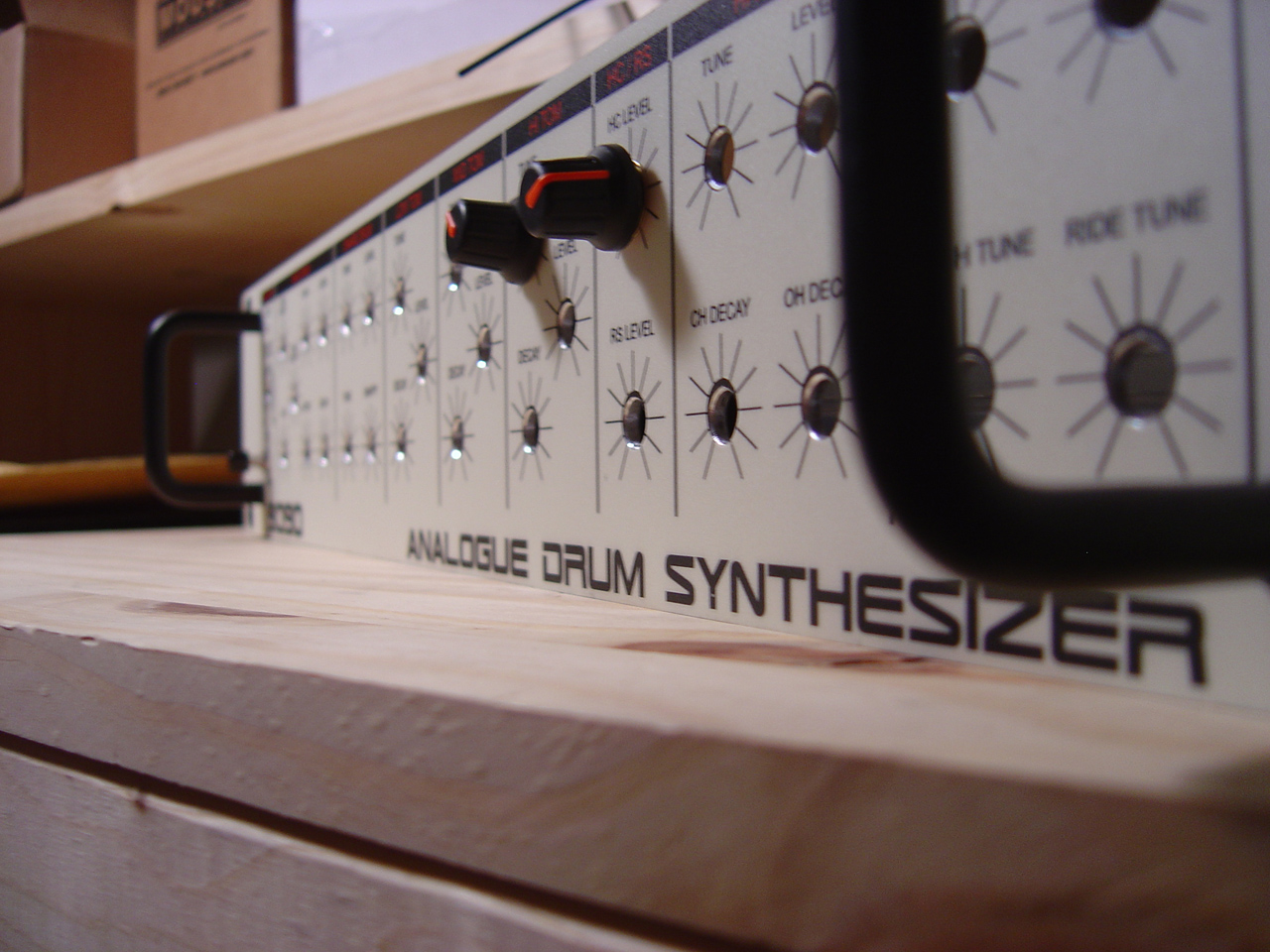
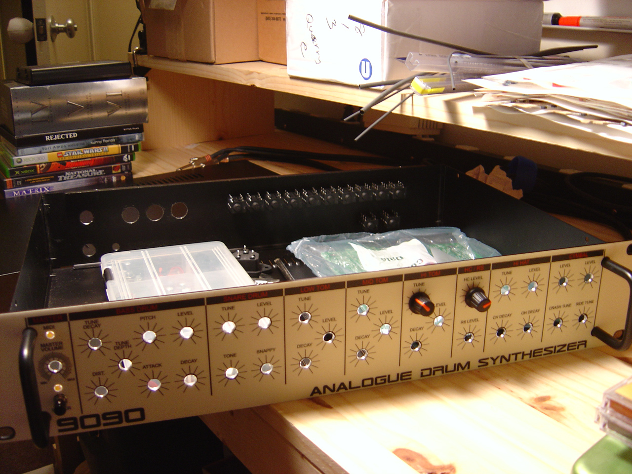
custom 9090 front panel graphic, for whatever it's worth, I got #1 in the run of 20.
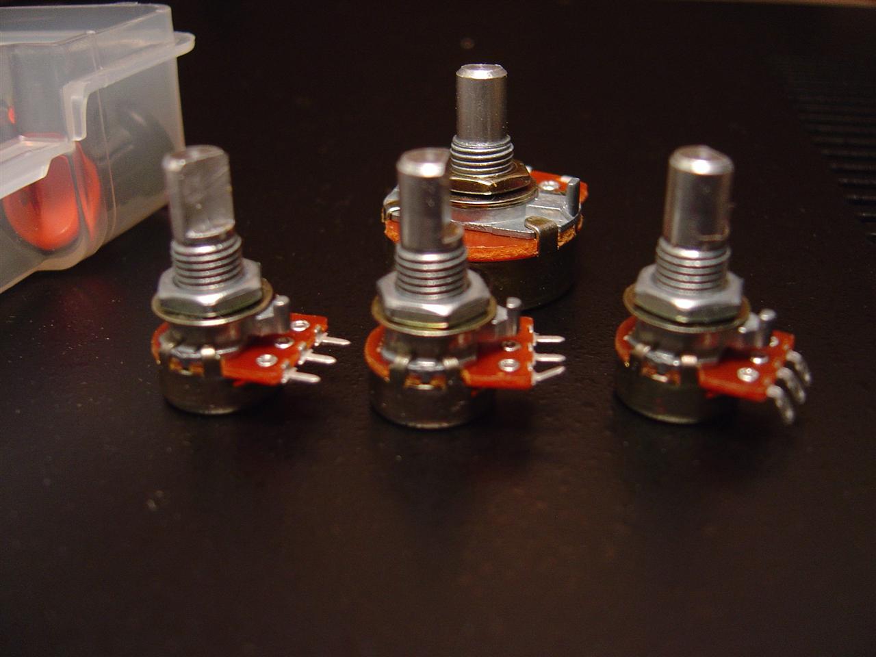
Steve also included 31 pots and knobs, a power switch, and some LEDs:

pots/knobs
Saturday 02.11.2007
3:00pm today, I install the pots. first, need to break off all the nubs on the pots, so they fit flush on the front panel. I use a vise grip and bend... they break of pretty easily, and with a clean line, this way.
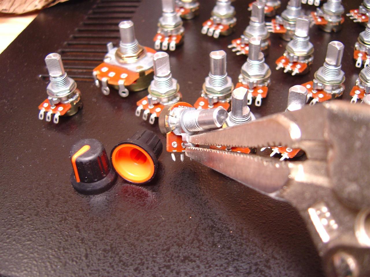
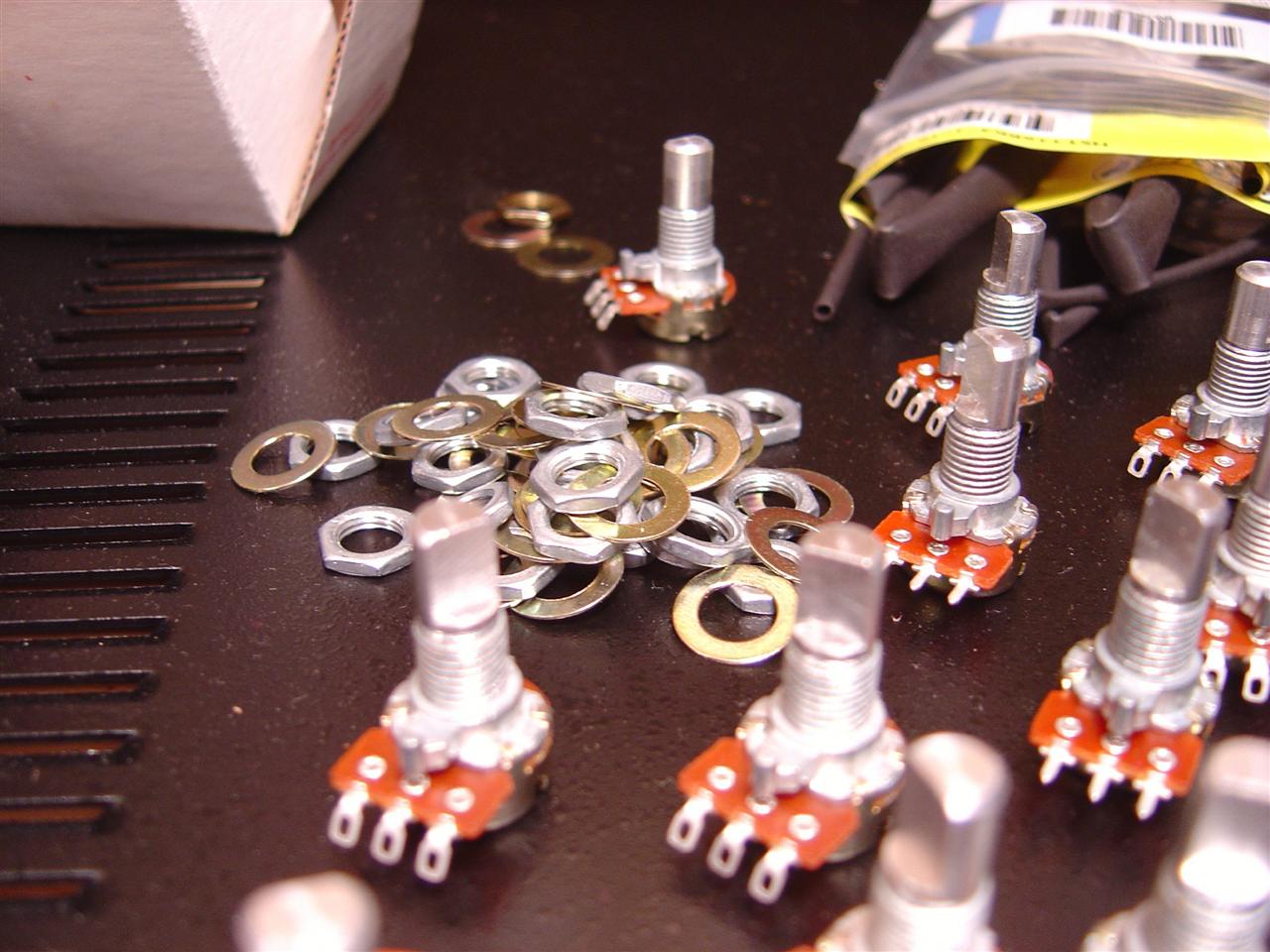
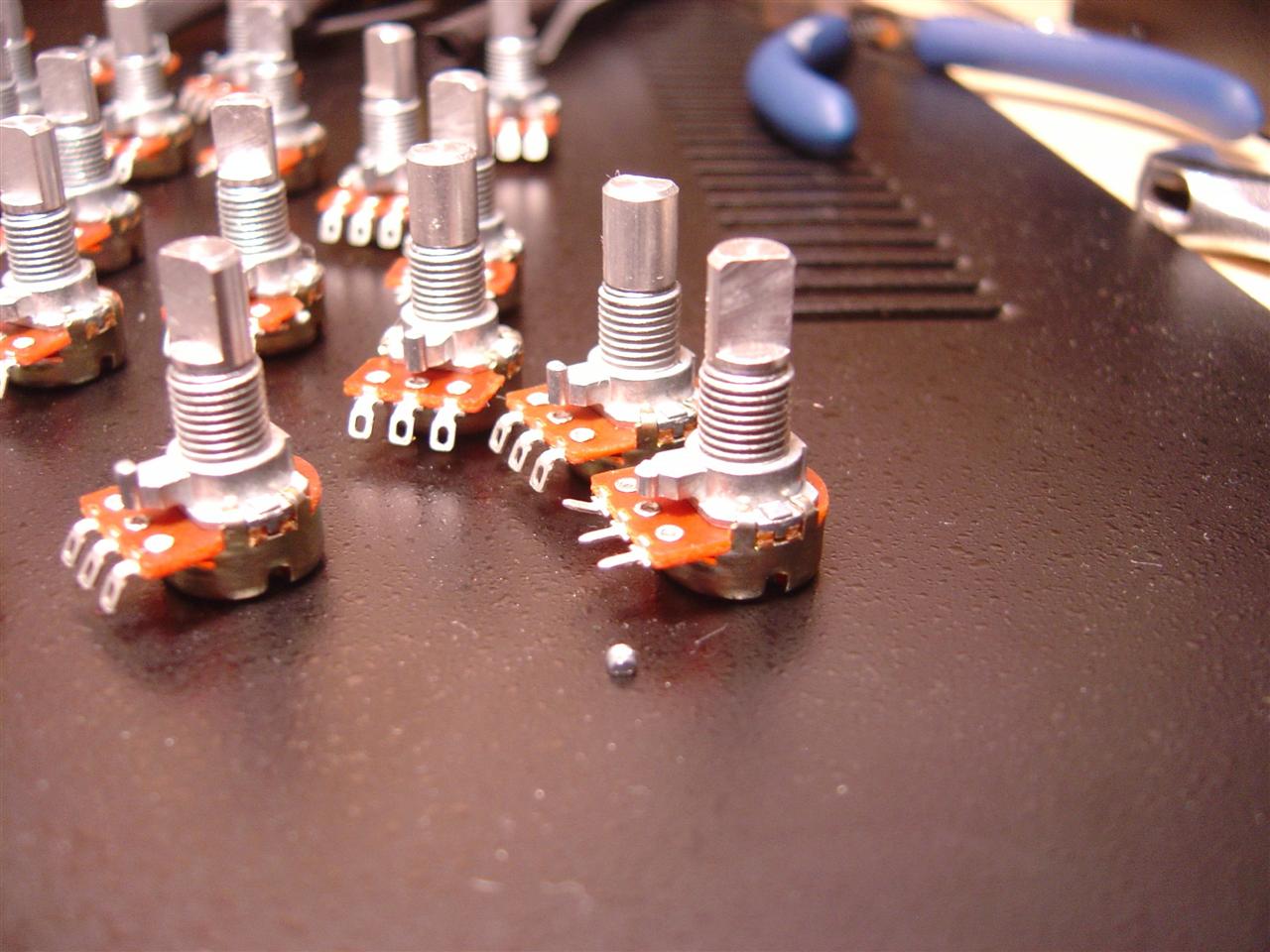
breaking off the nubs on the pots
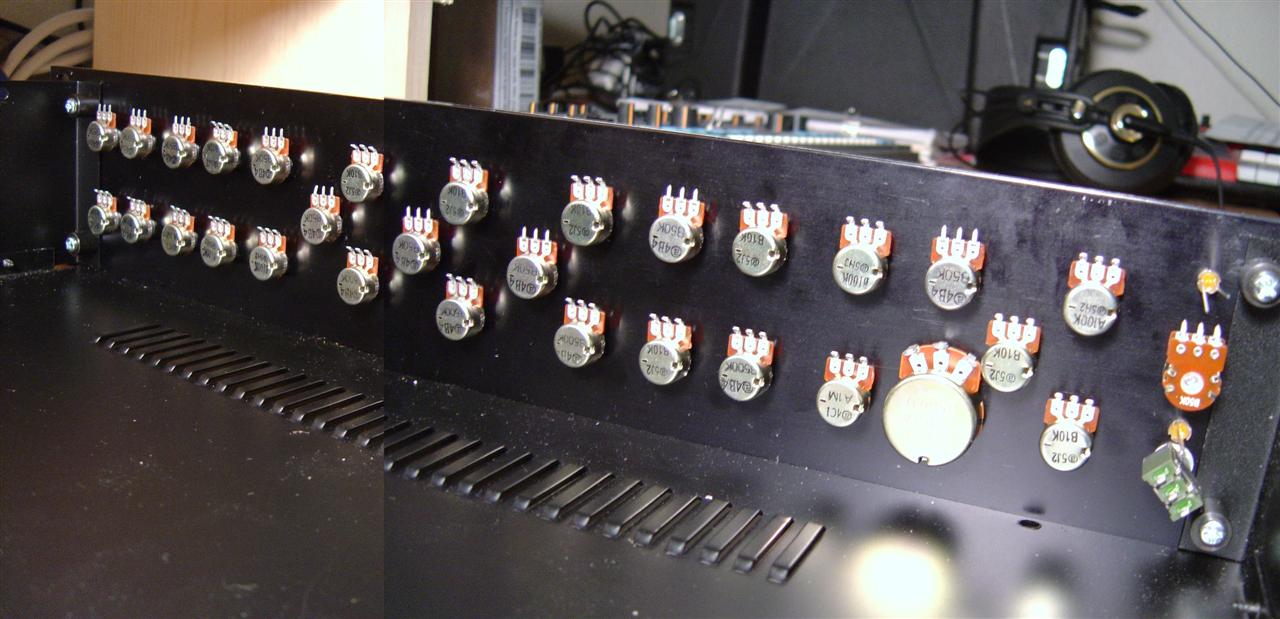
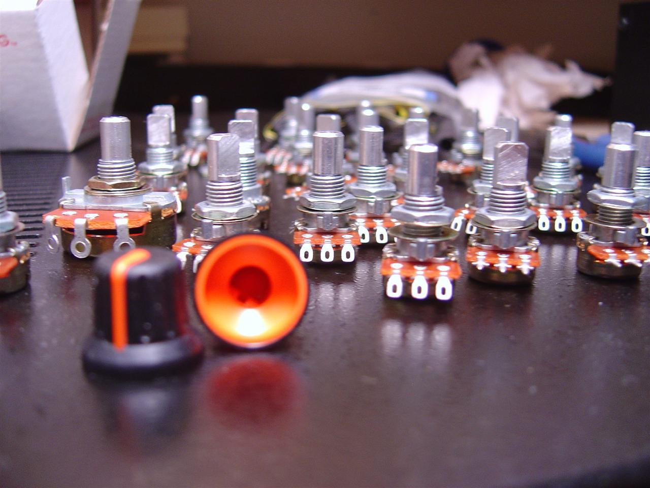
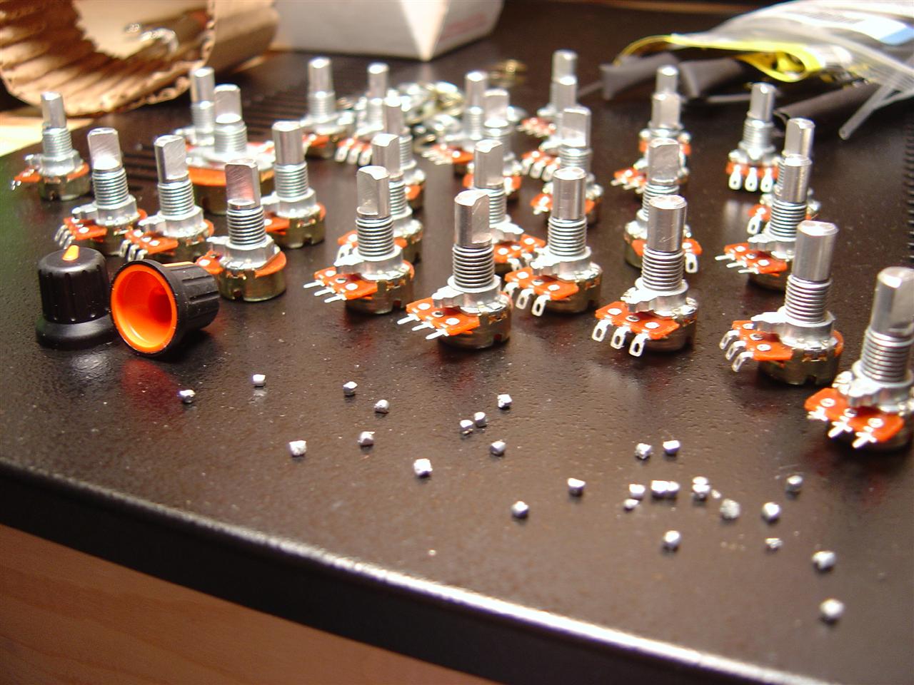
attach pots to the case

adding knobs
Apparently the knobs came from Mouser (though Steve says they were only available special order in large quantities). Steve also thinks you can get these knobs from Blacet in smaller quantities.
Sunday 02.11.2007
1:00pm I noticed that on the 9090 case the back audio jack holes (hehe, i said jack hole), don't match the PCB...
i'm just going to mount the pcb to the bottom of the case.
Also, the jacks I have don't match the PCB so two good reasons to mount the PCB to the case instead of the jacks.
(they're not the neutrik kind, and they're skinnier so they don't fit the PCB holes)
ah, hexagonal aluminum standoffs. i love you.
and here's more progress on building the case.
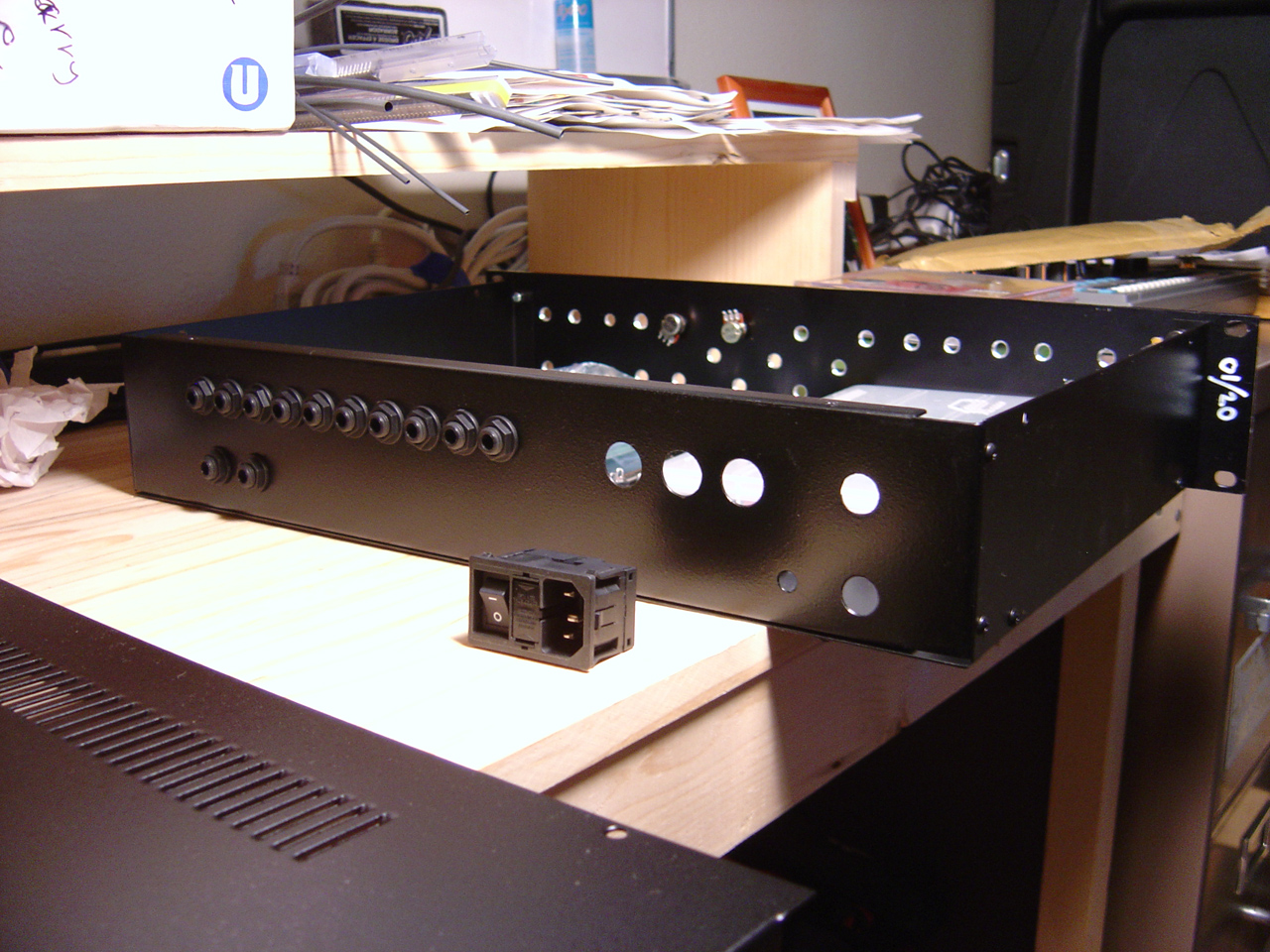
today I decided to install the power inlet. Instead of using the grommet and fuse socket provided by Steve, I decided to use one that has a built in switch and fuse holder, as well as an inlet jack for the power cord (detachable power cord == so sexy).
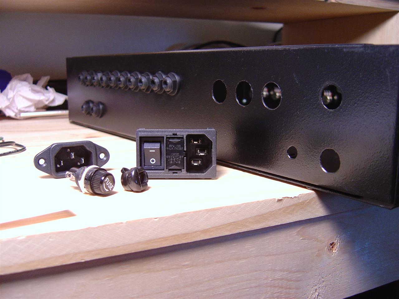
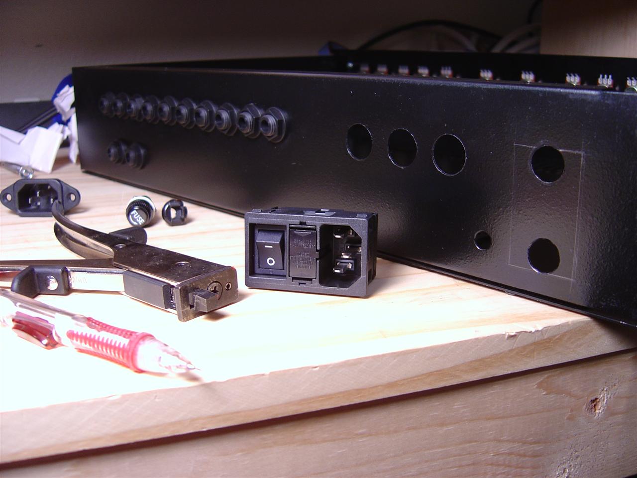
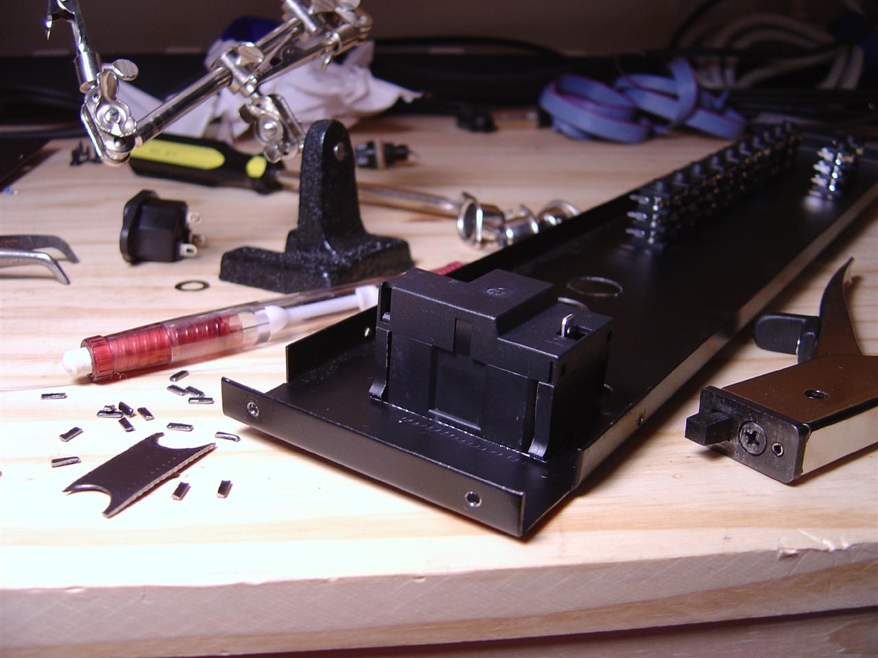
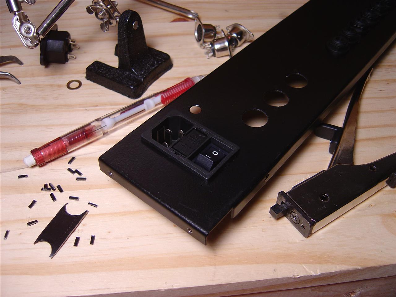
adding a power jack with mains-cutoff / fuse / inlet.
cutting a
hole with the nibbler tool
in the background you can also see the grommet and fuse that the case
came with
Thursday 02.15.2007
6:57pm
looking at these cool round midi jacks... (kind of expensive!) $5.23 http://www.mouser.com/catalog/629/918.pdf item 164-2522 (Deltron 5 pin threaded din jack with huge nut)
http://www.mouser.com/catalog/specsheets/0416191.pdf looks like I'd need to nibble out a detent in each midi jack hole so they don't spin freely... easy since I have a nibbling tool, unless it's too wide, we'll see...
might be just as functional using the crappy shiny flanged jacks, no one sees the back anyway... :-) my biggest concern is that they don't pull out or rotate freely, so i think i have these 2 options...
anyway, i'll probably tack them on next time i order from mouser. i like quality... :-/
update:steve clements says:
Have a peak here at DigiKey's 5 pin DIN panel mount locking receptical
http://rocky.digikey.com/scripts/ProductInfo.dll?Site=US&V=102&M=SD-50LS
http://dkc3.digikey.com/PDF/C071/P0344.pdf
These are 1/2 the price of the Deltron one's on Mouser
Sunday 04.29.2007
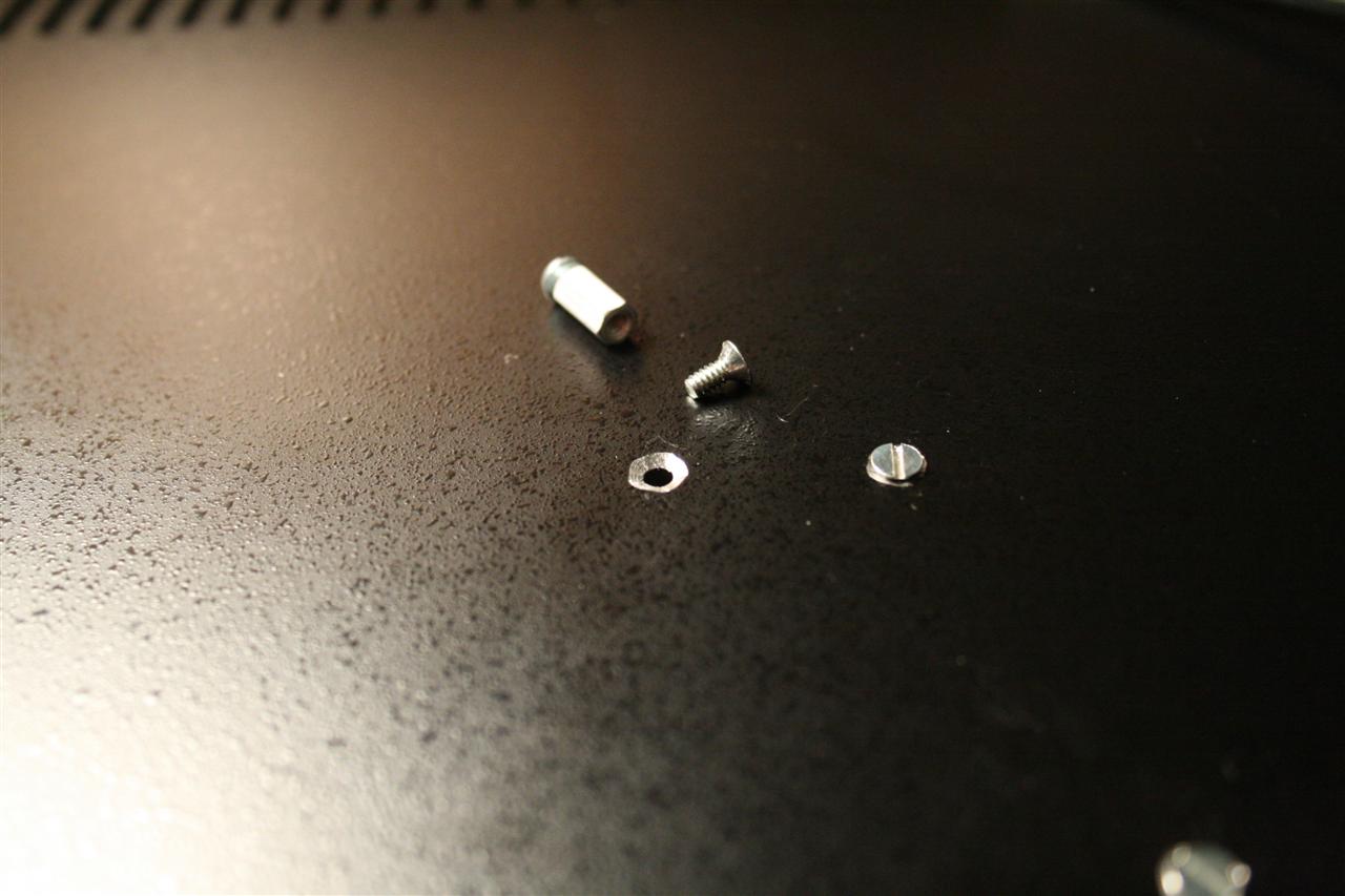
1:00pm Today I mounted the transformer and PCB boards to the 9090 case. I first drilled holes where I would screw on stand-offs, and countersinked them using a larger diameter drill bit (my screws were the countersinked kind 4-40 type 1/4" length).
Tricky part was where two holes intersected the vent (see picture), but this was easy enough. I ended up bending the vents out horizontally using a vise grip to make the bend accurately - pinching the two vent fins towards each other by a slight distance - "dialed in" using the visegrip tightness screw.
Still need the 3 MIDI Jacks mentioned above, and then the case is done...
6:35pm-7:35pm well, it's time to get started soldering this thing. before i can do that, i need some docs for reference, so tonight, I printed all the manuals, partslists, schematics for the 9090 from Trevor's website. Also pulled off some relevent things from the yahoo list, like some corrections to the schematics, and marco's guides for integrating original 909 parts into the 9090.
12noon Installed MIDI jacks (164-2522 @ mouser, Deltron 5 pin). Installed Fuse holders (576-83700000005 and 576-83400000000 @ mouser, littlefuse) onto the PCB (first solder!)... The fuse holders were the wrong size, but I made them work anyway by bending the leads.
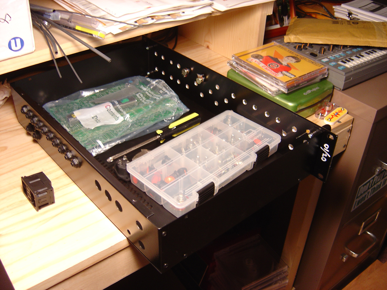
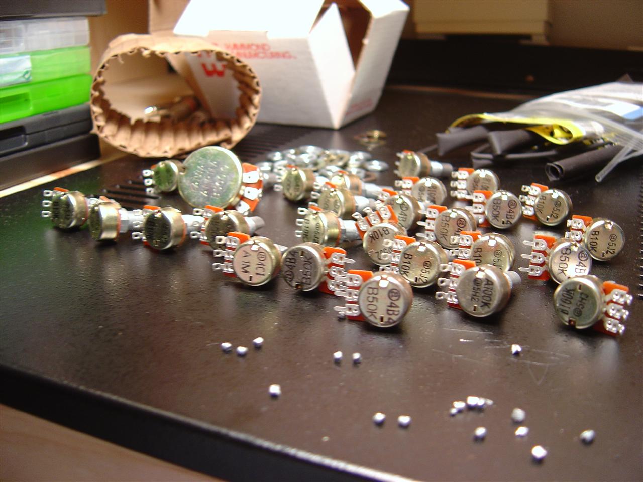
11am I realized that I wasn't going to be productive if I had to shuffle through my parts every time I wanted to find something. So I cleared out my work area, and spread the parts out:
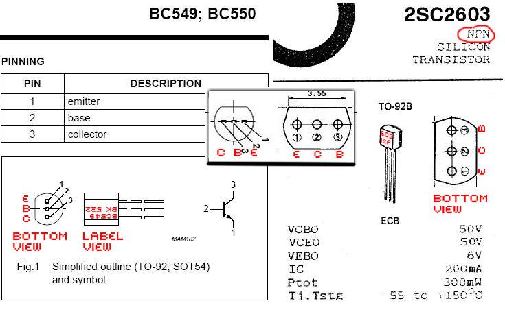
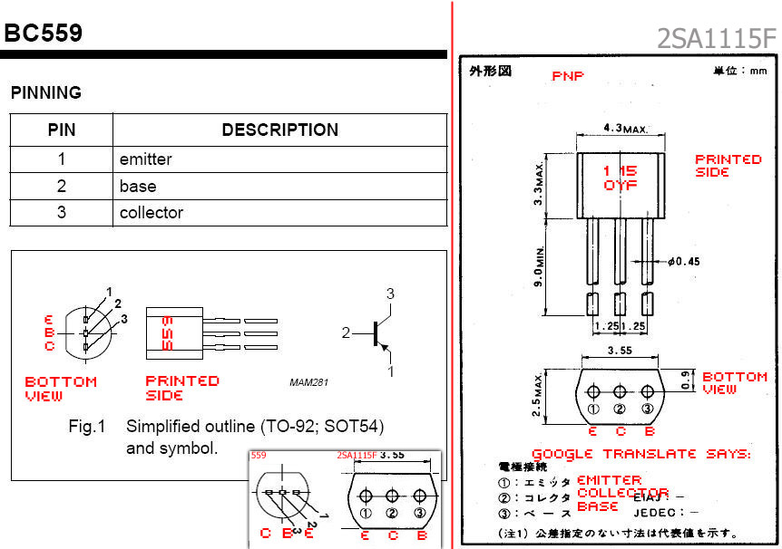
So, here in the BassDrum circuit we will substitute 2SA1115-F for the BC559 and substitute 2SC2603F for the BC549 transistor. To match the original part to the circuit board is somewhat tricky as the pins do not match. For 2SA1115-F and 2SC2603F simply swap pin 2 and 3, and then flip the transistor over, installing it with the flat label side backwards to the "D" graphic on the PCB. (refer to datasheets to be sure; "pin 2" and "pin 3" is found by counting left to right looking at the label with pins down).
Datasheet comparison
Reading Left To Right, looking at transistor label with pins down:
Testing hFE, comparing transistor pinouts:
The alternate parts seem to work. It sounds like a 909 bass drum, cool!
I hooked up the power and pots, only running PSU and bassdrum sections, headphones at the BD out and 0V, and hitting the trigger pin with 5V (with resistor attached in case there's too much current)...
All the knobs work except for the 2 knobs on J3:
For J3...
What's it sound like? it's more muffled than the harsh clipping of the 1N4148... In addition, there's a 3rd mode - no clipping diodes at all. which seem to let the transistor/opamp do the clipping, for a 3rd type of (really harsh and trashy) sound... the LEDs seem to round out the harshness of this opamp clipping (if that is what it is I'm hearing)... I may want to mess with this some more... but I do have 3 distint distortions, which is more fun than just one. :)
I'd like to try some different LEDs. The ones I used have a breakdown point of 2.7V, There are some with 2V or less breakdown, which should clip the waveform sooner before clipping the transistor/opamp (so all we get is sweet sweet LED distortion)...
update 06.13.2007: I measured voltage across a variety of diodes, and found some interesting results. Turns out the Purple LED I was using has one of the highest voltage of all of the LEDs I had laying around (making it not as effective, or clip as much, as the other types). Check it out:
So I wired in the "Dark Red Plastic" LEDs for their low breakdown voltage (voltage at which it allows current to flow, causing the signal to clip). The diodes, as used in distortion, are kind of like those drain holes we put on sinks so the water can't fill past a certain point... we'll see how it sounds later with the signal clipping earlier around this new 1.61V amplitude...
update 06.28.2007: it sounds much better than the purple LEDs...
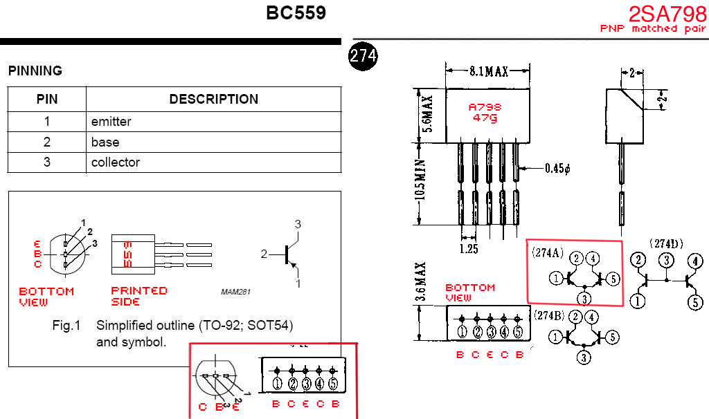
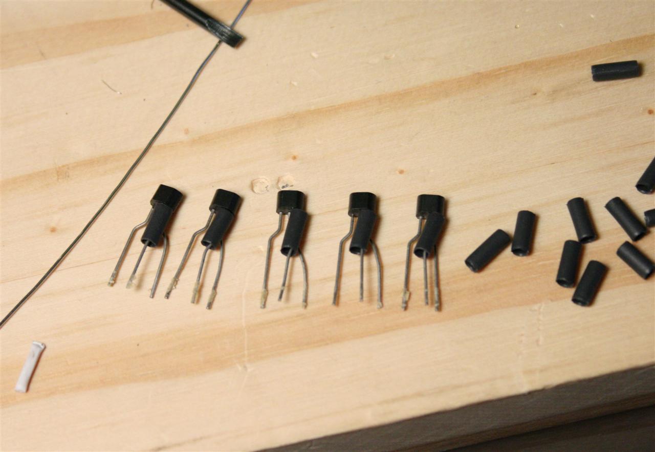
For the HC, HH, and Cymbal sections, I put in some original 909 parts instead of the 9090 parts: matched-pair transistors (the 2SA798) in place of BC559s. See the datasheet comparison, and pictured afterwards is how to bend the pins to plug into the PCB:
Along the way I noticed there were a few inaccurate quantities in the 9090 partslist so I'll need to order some of the missing parts and fill them in later. See if you can spot them below (ooo a game! you can tell i've been playing this game too much in the last many days)...
12midnight-12:30 Finished board #3. Figured I'd get this one done before bed, really quick and easy... I'm missing a few parts overall, including some connectors on this board. Will have to make an order, and install the missing pieces later.
To Order (missing pieces):
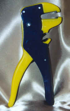
NOTE: a Helping Hand Tool is strongly recommended, an automatic wire stripper like this one will also speed things along. The helping hand tool alone will cut your time in 1/20, the crimp ends and wires are very small, and they tend to chase around the table! It can be the difference between frustration and eternal bliss.
9-12midnight wired up all 4 of the board001-to-board002 wires, velocity, triggers, power, and noise (I did the noise cable yesterday in the tutorial). On the power connector, I doubled up the ribbon cable 1.) to fit the spacing of the wider molex connector better, and 2.) it seemed appropriate to have a larger gauge wire for the power, it can't hurt at least...
I had some difficulty when making the connector ends, some of the crimp pins didn't feed very well into the connectors the first time. I found that when the crimps are easy to push in by hand they will go in straight. But if they're hard to push in, then they're probably going to get bent up inside the connector, so don't force it, it's best to back them out and try again more carefully... Getting it right the first time also seems to be key, since they scratch up the inside and this can make them travel to the same bent position over and over again inside the connector on subsequent tries.
I also wired up all 10 of the individual output jacks. I started by cutting 10 lengths of ribbon cable all the same size, then separating all the ends, then cutting some of the wires shorter for a better fit to the 1/4" jack and to the I/O PCB, then stripping all of them. I then tinned all the contacts on the I/O board, after which it was pretty easy to insert every wire (one after another) by heating each contact one by one. I then tinned all the leads that would attach to the 1/4" jacks, then attached all the leads in succession by melting them onto the 1/4" jacks...
Doing all 10 wires in this "assembly line" fashion was a very efficient and fast way to get this done.
11am - 4pm Spent some time packing up the missing parts for steve and chris (I did a 3x order for all of us). And documenting errors (see below list) that I found in the (5/Jan/04) 9090 parts list, and updating the spreadsheet. I uploaded these to the yahoogroup files section.
Inaccurate quantities can be found in several sections of the 9090 partslist from 5/Jan/04
Then I soldered in the missing parts... boards are now "done", or at least ready to power on and be tested. fingers crossed. (I still need to finish wiring up the pots to the boards).
11:30am - 6pm Finished wiring all pots/LEDs/front-powerswitch/mix-outputs... damn, that's a lot of work.
Ok, there are 2 problems I've noticed right away. The snaredrum doesn't trigger at all, and the bassdrum still has the problem with TuneDecay and Attack knobs not working.
the LED distortion does sound pretty cool. I'm glad I did this mod...
Here are some sound clips (minus SD, and BD Attack/TuneDecay):
9:00-3am So for the last 4 nights I've been trying to figure out the snare drum problem. 4 nights, probing with the multimeter and scope, understanding r@f's circuit analysis of the 909 (it's very interesting by the way, read it!). I finally figured out the problem, tonight after many long hours of poking, measuring, sleeping, eating, repeat... Turns out the problem was an easy one (aren't they always?), I had two transistors in the wrong spots next to Q18. Not that easy to spot apparently since I didn't see it...
Ok, so it was 2am, but what the hell, I was pretty happy so I thought I'd check out the BassDrum. I found this one in about 15 minutes. By checking continuity, starting at the misbehaving pots, I found that I had these pots connected to the header the wrong way, easy to swap the crimp pins...
Sound clips (SD/BD fixed):
Sound clips (BD):
I noticed the 9090 mixer amp does some really nice overdrive if you crank up the BD and the main volume with full LED distortion... mmmmm.. LED distortion. yummy!
Did the "rare parts" matter? I don't know. But it's fun knowing they're in there... They may be more trouble than they're worth, who knows, anyone want to compare samples?
Sequencer? yes, the 9090 comes with no built in sequencer. I have a MAMSQ16 that I'll try out with it. So far I've only used fruityloops for testing. The MAM will be interesting for sure. If I don't like it I may be selling it soon. :)

 Drilled holes on the 9090 case
Mounted boards and transformer
It's eerie, the case looks so naked. It's screaming "I need transistors!"
Sunday 05.06.2007
printing docs for the 9090, it's time to get started...
Monday 05.07.2007
8:35pm-10:35pm added connectors to the mains transformer. crimped spade connectors on the 115V side, and molex on the 15-0-15 side. I filled in one of the spaces on the molex connecter (with epoxy) so that it is "keyed" to only fit in one slot on the 9090 PCB - to prevent insertion at any other point (which could destroy stuff. :) )...
"keying" the molex connector for the AC 15-0-15 side of the transformer
(so we don't accidentally plug this into another jack)
crimped spade connectors on the 115V side of the transformer - hooked into the power inlet.
Friday 05.11.2007
installed MIDI jacks
I had to bend the FUSE holder leads unevenly (to one side, see 3rd picture), and sand them flat on one side, so they would fit together on the PCB
First solder! Here's the 9090 assembly bench...
Saturday 05.26.2007
8pm finished the PSU section. I plugged in and turned on the 9090 to test that the AC 15/0/15 is converting properly to DC 15/5/0/-15V. There seems to be a problem, we're getting DC 15/5/0/-16.7V ! not sure why, maybe a bad 7915 regulator?... :( I plan to fix this before moving on...
testing the PSU section - results: 15V, 5V, -16.7V ???
Sunday 05.27.2007
12noon I got an idea from Trevor that maybe the 7915 would behave better under load (and reading the datasheet, it says it's meant to operate within 5mA to 1.5A, so this is probably true). I added a 470ohm resistor across 0 and -15 (for 31mA current draw I=V/R), and yes the voltage changes! to -15.3V. pretty close, but not -15V... Trying 100ohm doesn't change the voltage reading, so I think I'm stuck at -15.3V for negative (by the way, the 100ohm got pretty hot so I didn't leave it on for very long)...
PSU under load -15.3V ???
Saturday 06.09.2007
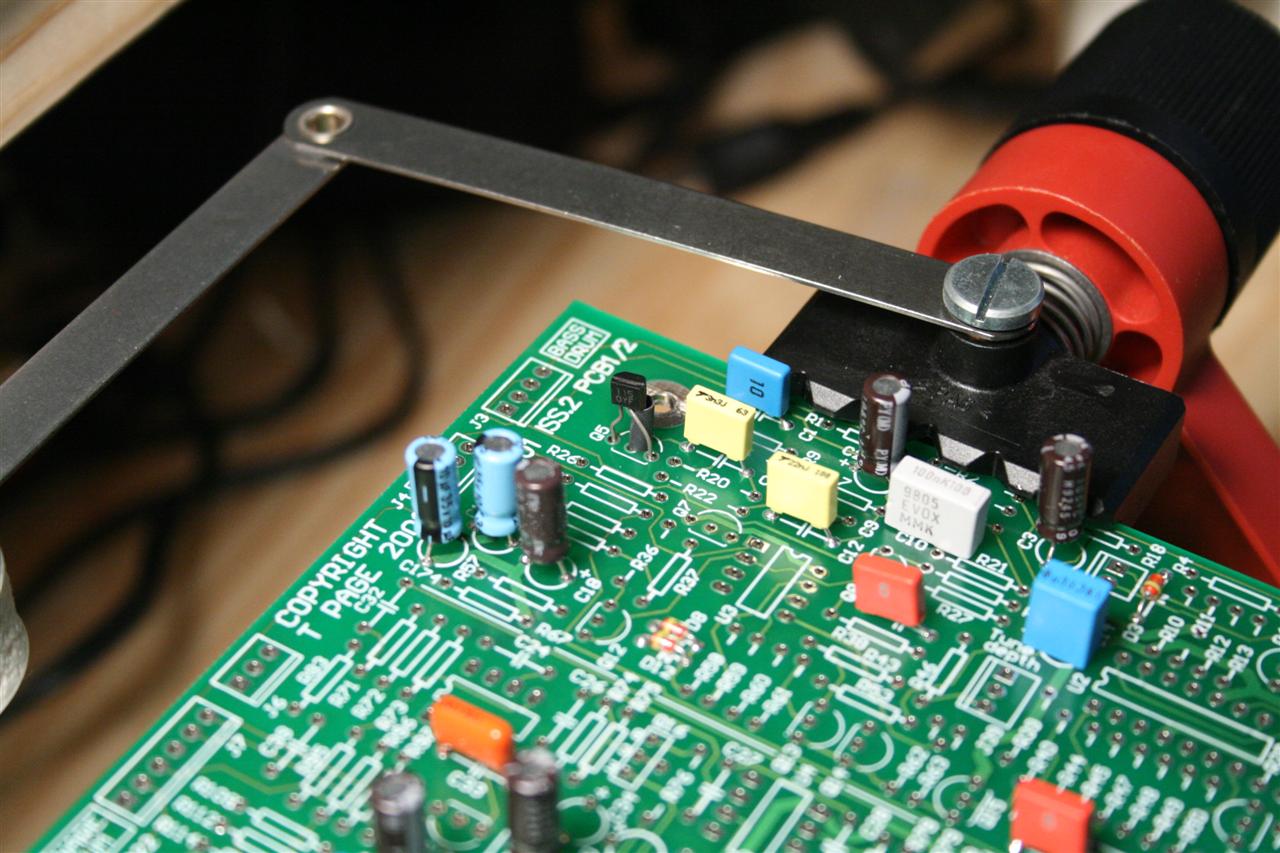
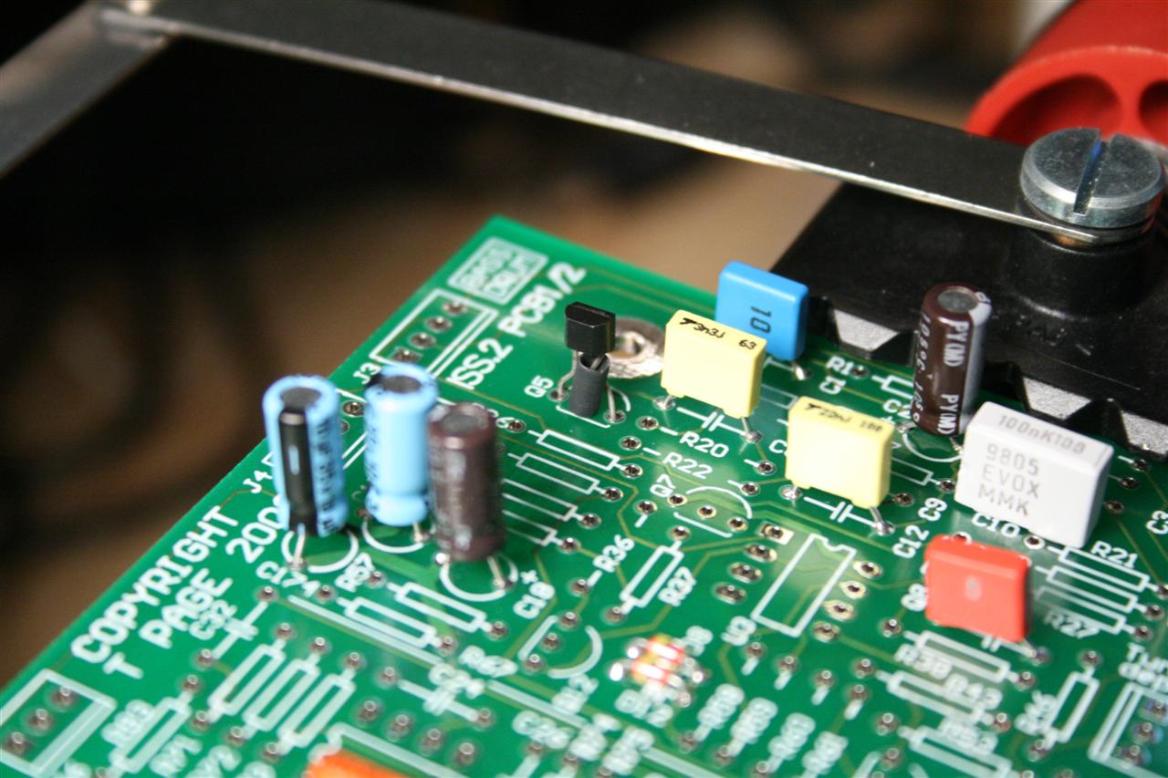
starting work on the BassDrum section, parts are laid out!
started bass drum section, caps first, diodes, resistors, then transistors/ICs. For the transistors, we have something special to do. i got in on a group-order for the original 909 Japanese parts. Some of the parts in the 909 have been discontinued, and so the 9090 makes certain part substitutions. The older parts will replace some of the "modern" 9090 parts, mostly transistors, some opamp ICs, and diodes. The hope is to make the 9090 closer to the original 909 it's trying to clone. The part substitution affects nearly every section/instrument on the drum sysnthesizer, so I'll be doing the part substitution throughout this worklog and will only mention this fact again for each new part introduced along with datasheets and instructions for how to install...
Using the original 909 Japanese parts in place of modern 9090 parts...
For the transistors - swap pin 2 and 3 and flip over (don't put it in the wrong way)
BC559 is 321 = CBE
2SA1115F is 123 = ECB
1.) BC549/2SC2603F npn transistor comparison
2.) BC559/2SA1115-F pnp transistor comparison
BC559
(it would read "CBE" when looking at the label with pins down).
2SA1115-F
pins 2 and 3 swapped here, label facing opposite direction from the BC559
(unbent, it would read "ECB" when looking at the label with pins down)
Sunday 06.09.2007
9:30pm - 1am I wired up the pots and powered it up!
Tune Depth and Attack don't seem to do anything at all.
I'm guessing it's because velocity-in isn't hooked up? (could this be right?)
I see continuity from the pot pins to [R2, GND, Q8, R1] (corresponding to J3 pins [1,2,3,4] respectively)
My pots are good, (I see varying resistance when I turn them)...
Finished bass drum section
Creating the wires for the front panel pots...
Wired up for testing - (headphones green/yellow, trigger red)
Monday 06.12.2007
8:30 - 11:30pm Distortion selector mod. I'm only two sections done, and already it's mod time! I decided I wanted to play around with different clipping diodes, and their effect on distortion, I ended up adding a new switch to the front panel! And inside are 2 new LEDs (as clipping diodes). The switch can select between back-to-back 3mm purple LEDs or the stock 1N4148 diodes spec'd out in the current 9090 design. Check it out:
Distortion typeselector switch (mod) is wired, 2 diodes and 2 LEDs. I didn't need to use a DPDT switch here, but it's what I had...
Installed Header/Connector pins in diode's old location at D1 and D2.
Installed mini switch on the front panel, near the distortion gain knob.
LEDs
Strange yellow     3.4V   (6 little LEDs in one LED-size light, neat)
Purple Clear 3mm   2.78V
Blue  Clear        2.74V
White Clear        2.63V
Green Clear        2.47V
Green Plastic 3mm  1.79V
Red Plastic        1.79V
Red Plastic 3mm    1.78V
Yellow Plastic 3mm 1.75V
Red Clear          1.67V  (this LED came with the x0xb0x kit)
Dark Red Plastic   1.61V

Diodes:
SRM-8Z Diode       3.88V  (from a microwave oven :)
1N4148 Diode       0.57V
1N4007 Diode       0.53V
Germanium Diode    0.27V
Distortion type selector, now with Red!
Tuesday 06.12.2007
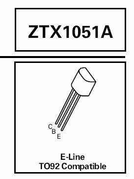
9pm - 12pm Started and finished the SnareDrum section. I'm using the (rare part) 2SD1469 transistor. Only snag was finding a datasheet for the 2SD1469. Luckily I found 1 image using google image search. A suitable replacement for this transistor is the ztx1051a (reading the mailing list archives, Trevor says it tests nearly identical sounding to the 2SD1469), but you would need to swap the B and C pins on the ztx1051a to make it match the PCB holes which are apparently designed for the rarer 2SD1469.
1.) Datasheet for 2SD1469 (english translation added)
2.) How to orient the 2SD1469 transistors on the 9090 PCB
Finished snaredrum section
Wednesday 06.13.2007
7pm - 12:30pm Started and finished the Low and MidToms sections! I found that I had a missing part, see if you can spot (the lack of) it.
Finished LowTom section
Finished MidTom section
Friday 06.15.2007
7pm-12am Tonight I finished board #1 - Noise and Amp sections, and started board #2 by finishing the MIDI section.
Finished Noise section
Finished Amp section
Board 001 finished!
Started PCB 002... Finished MIDI section
Saturday 06.16.2007
7pm-11pm Tonight I finished the HighTom section.
Finished HighTom section
Sunday 06.17.2007
12noon-10pm Today/Tonight I finished board #2, HandClap, RimShot, HiHat, and Cymbal sections.
Comparing BC559/2SA798 datasheets
How to install the 2SA798 matched-pair transistors: requires some bending of pins...
Finished RimShot section
Finished HandClap section
Finished HiHat section
Finished Cymbal section
Finished Board #2, now in the case!
Sunday 06.17.2007
Finished Board #3 (minus a few parts I need to order)
qty| part                | comment (what happened?)
---+---------------------+-----------------------------------
6x  10uF                   (9090 BOM quantity was inaccurate)
1x  390pF                  (9090 BOM quantity was inaccurate)
7x  100pF                  (I forgot to order these)
1x  56nF                   (9090 BOM quantity was inaccurate)
1x  1nF                    (9090 BOM quantity was inaccurate)
4x  4011UB                 (need unbuffered! I had 4011BE)
1x  10kb bournes trimpot   (I forgot to order this)
2x  6pin polarized header  (9090 BOM quantity was inaccurate)
1x  4pin polarized header  (9090 BOM quantity was inaccurate)
1x  3pin polarized header  (9090 BOM quantity was inaccurate)
This was about $25 at mouser before shipping, including extras of each part...
soldering aftermath - and this is what your bench looks like when you're all done
Monday 06.18.2007
CABLE MAKING TUTORIAL
12midnight-12:20 I decided to make a little tutorial for making cables. This can be very tedious and frusterating to do without the right tools, but here I'll show how easy it is, in about 10-15 minutes I made a 4 conductor cable...
1.) Separate wires by clipping in between
2.) remove insulation the best way you know how
3.) Repeat for the other end
- in case you clip something short and don't have enough wire to use,
now is the time to mess it all up before you've invested too much time!
(I use the pictured tool for both tasks, 8 clips, then 8 gentle pulls)
IMPORTANT: strip away only a few milimeters of wire so that it will fit in the crimp pin..
Tin the ends of every wire
This is essential for a quick/easy stick to the crimp pin later!
Cut off enough crimp pins, again, same tool as above makes this fast and simple...
1.) Secure the crimp pin in the aligator clip.
Lay the wire down with tinned part in the 'tray', and insulation in the 'crimp'.
Use a fine tip solder point and melt the tinned wire to the 'tray'.
2.) Repeat #1 for the other 3 pins.
3.) Now that the wires are secure, crimp the pins onto the insulation to relieve stress on the solder joint - using a pliers.
1.) Insert the crimp ends into the connector, make sure they go in totally straight and aren't bent in the slightest.
2.) Halfway there...
3.) Press them down the rest of the way with a tiny screwdriver (pressing onto the crimp metal) until a click is heard
Finished cable... First one done, many more to go...
Tuesday 06.19.2007
Saturday 06.23.2007
Here are the corrections (with updated partslist spreadsheet):
qty    part         section   wrongQty
------------------------------------------
1      0.33uF       BassDrum  (2)
5      TL072        MidTom    (6)
16     1N4148       HiTom     (18)
3      1nF          HandClap  (2)
2      10uF         HiHats    (1)
7      10uF         Cymbals   (4)
2      390pF        Cymbals   (1)
2      4011UB       Cymbals   (3)
5      10uF         Amplifier (3)
7      6pin header  ICsockets (5)
20     4pin header  ICsockets (19)
6      3pin header  ICsockets (5)
Sunday 06.24.2007
Finished "stereo mix" output jacks... Assemble, then install...
Finished interconnect wiring...
After doing a few quick checks to be sure there's no shorts to ground at the power connections or at the audio outputs... I powered it on, the MIDI light flashed a few times (initializing with defaults for the first time, says the user manual), and after I figured out I needed to use channel 10 (!!), it sounds really great!
![]() 1sttake.mp3
1sttake.mp3
![]() 2ndtake.mp3
2ndtake.mp3
Sunday-Thursday
Here's what happened. Hopefully this image helps someone avoid the same mistake.
SnareDrum schematic with my notes, TODO lists and scribbles as I worked on the problem
My measurements say why it didn't work, but I didn't realize it at the time,
see if you can spot it (hint... 9VDC)
yes, I removed and replaced all transistors, diodes, opamps while tring to fix the SD...
When I did the transistors I left them "loose" so I could experiment, after about 10 minutes I found the problem by moving and poking at transistors
![]() sd.mp3 (snare drum works!)
sd.mp3 (snare drum works!)
![]() heavy.mp3 (demo after bassdrum was fixed)
heavy.mp3 (demo after bassdrum was fixed)
![]() BDclean.wav (BD clean)
BDclean.wav (BD clean)
![]() BDdiodes.wav (BD std distortion)
BDdiodes.wav (BD std distortion)
![]() BDled.wav (BD LED distortion)
BDled.wav (BD LED distortion)
![]() BDnodiode.wav (BD distortion w/ no diodes)
BDnodiode.wav (BD distortion w/ no diodes)
![]() BD-many.wav (assortment of hits)
BD-many.wav (assortment of hits)
Conclusion
Overall, a pretty long project. Distilling the parts list, Sourcing parts at mouser/futurlec/newark/digikey, Assembling the case (that SteveM designed/made for us, wow thanks!), and finally soldering in all the parts and creating wires. Debugging can be confusing with the many parts as well as I wasn't used to thinking about transistors. The users/builders mailing list is small as well, which means little to no hand holding when problems come up. For the pure attention span required alone, I'd say this is an advanced project, plus all the long tedious manual steps required. This is no kit, but I was fortunate to have PCBs and a case made for me.
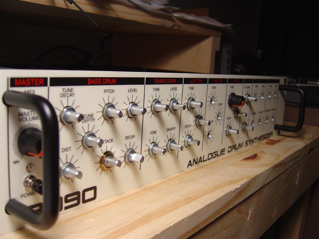
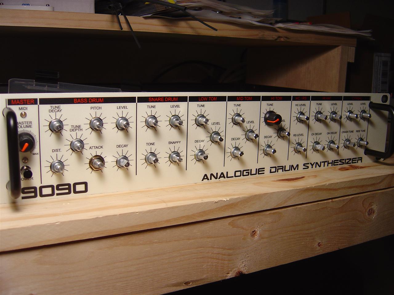
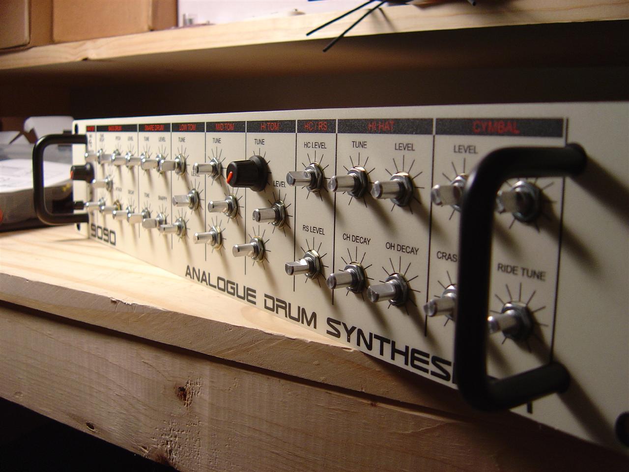
Final Pictures
Future Work
I really should find some way to label the rear panel that looks attractive... I'd also really like to add decay knobs to the snare drum and rimshot. Maybe dedicated distortion knobs too...
Links